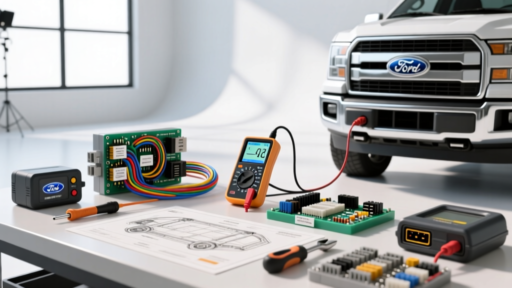
The Reality of Ford F150 Electrical Problems
When diagnosing Ford F150 electrical problems, a generic approach will inevitably lead to misdiagnosed modules, blown fuses, and hours of wasted labor. Ford's truck lineup utilizes complex multiplexed networks—including High-Speed CAN (HS-CAN), Medium-Speed CAN (MS-CAN), and newer LIN bus architectures—that require specialized diagnostic equipment. Whether you are tracking down a parasitic battery drain in a 2013 F-150 Body Control Module (BCM), diagnosing a corroded Powertrain Control Module (PCM) connector on a 2006 5.4L V8, or troubleshooting aluminum-body ground faults on a 2016 model, selecting the correct diagnostic tool and replacement hardware is critical.
This selection guide compares the industry-standard multimeters, bidirectional OBD2 scanners, and wiring repair kits specifically suited for resolving Ford F150 electrical problems. We will break down the technical specifications, AWG requirements, and module-level diagnostics needed to fix these trucks right the first time.
Digital Multimeters (DMM) vs. Circuit Testers: Selecting Your Primary Weapon
Voltage drop testing is the cornerstone of F-150 electrical troubleshooting. Relying on a standard test light or a basic $20 multimeter will not reveal the high-resistance faults common in Ford's 18 AWG Black/White (BK/WH) ground circuits. According to the Fluke Automotive Voltage Drop Testing Guide, a healthy circuit should exhibit less than 0.1V drop per connection or splice.
Tool Comparison Matrix: Automotive Multimeters
| Feature | Fluke 88V Automotive DMM | Power Probe IV | Klein Tools MM400 |
|---|---|---|---|
| Min/Max Recording | 100ms (Captures intermittent CAN faults) | N/A (Real-time only) | N/A |
| Impedance | 10 Megohm (Safe for PCM logic) | Variable (Risk of backfeeding) | 10 Megohm |
| Duty Cycle / RPM | Yes (Essential for Ford COP ignition) | Yes | No |
| Best F-150 Application | PCM sensor testing, CAN bus validation | Actuating window motors, fuel pumps | Basic battery/alternator checks |
Expert Verdict: For diagnosing Ford F150 electrical problems related to the PCM or BCM, the Fluke 88V is mandatory. Its 100-millisecond Min/Max capture rate allows you to catch micro-second voltage drops on the 5V Reference (VREF) circuit—typically a Brown/White (BN/WH) wire on Ford sensors. Conversely, the Power Probe IV is excellent for directly powering up a suspect driver-side window motor or fuel pump relay, but its internal power supply can easily backfeed and fry a Ford module's logic board if used on low-voltage CAN lines.
Bidirectional Scanners for Ford Module Networks (CAN/MS-CAN)
Ford F150 electrical problems often stem from a module failing to enter 'sleep' mode, causing a parasitic drain. A standard OBD2 scanner only reads the HS-CAN bus (Engine, Transmission, ABS). To diagnose the MS-CAN bus (which handles the BCM, Instrument Cluster, and APIM/SYNC module), you need a scanner capable of dual-bus communication.
OBDLink MX+ vs. Autel MaxiCOM MK808
- OBDLink MX+ (Paired with FORScan Software): This is the gold standard for Ford diagnostics. The MX+ features an automatic MS-CAN/HS-CAN toggle, meaning you do not have to manually flip a switch on the adapter to read the BCM. Using FORScan, you can perform a network test to see exactly which module is keeping the CAN bus awake. If your 2011-2014 F-150 draws more than 50mA after 45 minutes of key-off sleep, FORScan will identify the offending node. Read more about dual-bus protocols on the FORScan Official Protocol Documentation page.
- Autel MaxiCOM MK808: A fantastic standalone tablet scanner with excellent bidirectional controls. It allows you to command the Ford Integrated Wheel Ends (IWE) solenoids or cycle the HVAC blend door actuators. However, it requires expensive annual subscriptions for advanced module programming (PMI) and is less transparent when viewing raw MS-CAN hex data compared to FORScan.
OEM vs. Aftermarket Wiring Pigtails and Connectors
One of the most common Ford F150 electrical problems involves water intrusion into the PCM connector (specifically C1381b on the 2004-2008 5.4L V8 engines). Water wicks down the harness, corroding the VPWR (Pin 16, Red wire) and TACH (Pin 71, Gray/Black wire) terminals. When it is time to replace the pigtail, the product you select dictates the longevity of the repair.
Motorcraft WPT-1246 vs. Dorman 645-932
- Motorcraft OEM Pigtails: Motorcraft uses exact OEM wire gauges (usually 18 AWG for sensor circuits and 14 AWG for power feeds). Crucially, they include the proper internal silicone weatherpack seals and terminal tensioners. When repairing a PCM ground (Pin 25, Black/Yellow), the OEM seal prevents capillary action from pulling moisture back into the connector.
- Dorman Conduct-Tite: While cheaper and widely available at local parts stores, Dorman pigtails often utilize 20 AWG wire for circuits that require 18 AWG. This two-gauge difference increases resistance, leading to a voltage drop that can trigger false P0121 (Throttle Position Sensor) codes. Furthermore, aftermarket kits frequently lack the secondary locking tab (TPA) required to keep terminals seated in Ford's high-vibration engine bay connectors.
Expert Verdict: Always source from the Motorcraft OEM Wiring Catalog for PCM, BCM, and airbag (RCM) repairs. Reserve aftermarket kits for low-stakes circuits like trailer lighting or aftermarket accessory taps.
Troubleshooting Decision Tree: Symptom to Solution
Use this structured decision tree to match your specific Ford F150 electrical problem with the correct diagnostic tool and repair strategy.
- Symptom: 2015+ Aluminum Body F-150 experiencing random stalling, dimming headlights, and U-codes (Network Communication faults).
- Diagnostic Tool: Fluke 88V (Voltage Drop Test on Grounds).
- Target Area: G100 (Engine Block) and G104 (Cab Ground).
- Fix: Aluminum oxidizes rapidly, creating a high-resistance barrier. Remove the ground bolt, clean the chassis with a stainless-steel wire brush, apply aluminum-safe anti-oxidant paste (e.g., NOALOX), and reinstall using a new star washer to bite through the oxide layer. Do not use standard copper grease on aluminum.
- Symptom: 2004-2008 F-150 5.4L cranks but has no spark, no fuel injector pulse, and no communication with the PCM.
- Diagnostic Tool: Test Light & Fluke 88V.
- Target Area: PCM Connector C1381b, Pin 16 (VPWR).
- Fix: Check for 12V at Pin 16 during crank. If voltage drops below 10.5V, trace the Red wire back to the PCM diode and Central Junction Box (CJB). If voltage is present but the PCM is unresponsive, inspect for green crusty corrosion on the pins. Clean with CRC QD Electronic Cleaner and apply Motorcraft dielectric grease.
- Symptom: 2011-2014 F-150 battery is dead every morning (Parasitic Drain).
- Diagnostic Tool: OBDLink MX+ with FORScan & Fluke i410 Current Clamp.
- Target Area: Passenger Compartment Fuse Panel, Fuse 27 (BCM) and Fuse 33 (APIM/SYNC).
- Fix: Clamp the negative battery cable. Wait 45 minutes for modules to sleep. If draw remains above 50mA, pull Fuse 33. If the draw drops, the APIM (SYNC module) is failing to sleep and requires replacement or firmware flashing via FORScan.
Conclusion
Solving Ford F150 electrical problems requires moving beyond basic code reading and embracing systematic circuit validation. By investing in a high-impedance DMM like the Fluke 88V, utilizing dual-bus scanners like the OBDLink MX+ for deep module diagnostics, and refusing to compromise on Motorcraft OEM wiring pigtails, you ensure that your repairs withstand the harsh vibrations and environmental exposures unique to Ford trucks. Proper tool selection is not just about convenience; it is about protecting the highly sensitive, multiplexed networks that keep modern F-150s on the road.