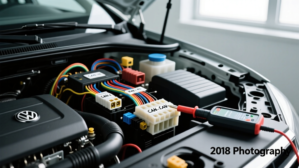
Understanding the Root of VW Jetta Electrical Problems
Volkswagen Jettas are renowned for their driving dynamics, but they are equally notorious for complex electrical gremlins. When owners search for solutions to VW Jetta electrical problems, they are usually battling cascading failures stemming from the Comfort Control Module (CCM), the Data Bus Diagnostic Gateway, or degraded ground points. Unlike domestic vehicles that rely on simple, direct-switched 12V circuits, modern Jettas (particularly the Mk4, Mk5, and Mk6 generations) utilize multiplexed CAN-bus networks to manage everything from power windows to interior lighting. A single compromised wire in this network can cause a domino effect of seemingly unrelated electrical faults.
To properly diagnose these issues, you must abandon basic test-light logic and adopt a systematic wiring diagram walkthrough approach. This guide will decode Volkswagen’s specific DIN wiring standards, walk you through the critical Gateway pinouts, and provide a definitive diagnostic decision tree for the most common Jetta electrical failures.
DIN Color Codes and Metric Wire Sizing
Before tracing any circuit on a VW wiring diagram, you must understand the German Industrial Standard (DIN 47002) color codes and metric wire gauges. Misinterpreting these will lead to immediate diagnostic dead ends.
VW Wire Color Abbreviations
- sw = Black (Schwarz)
- rt = Red (Rot)
- bl = Blue (Blau)
- gn = Green (Grün)
- ws = White (Weiß)
- ge = Yellow (Gelb)
- br = Brown (Braun)
- or = Orange (Orange)
- li = Violet (Lila)
- gr = Grey (Grau)
Note: A dual-color wire is written with the base color first and the tracer color second (e.g., or/sw is Orange with a Black stripe).
Metric to AWG Cross-Section Reference
Volkswagen specifies wire size in square millimeters (mm²). When sourcing replacement wire or crimp connectors, use this conversion chart to match SAE AWG standards:
- 0.35 mm² ≈ AWG 22 (Used for low-current sensor signals)
- 0.50 mm² ≈ AWG 20 (Standard for CAN-bus and module logic)
- 1.00 mm² ≈ AWG 18 (General lighting and low-draw accessories)
- 1.50 mm² ≈ AWG 16 (Fuel pump, power mirrors, interior fans)
- 2.50 mm² ≈ AWG 14 (Power seats, high-draw lighting)
- 4.00 mm² ≈ AWG 12 (Main power feeds, rear defroster)
- 6.00 mm² ≈ AWG 10 (Heavy ground straps, starter circuits)
Complete Wiring Diagram Walkthrough: The Data Bus Gateway
The Data Bus Diagnostic Gateway (often integrated into the instrument cluster on Mk4s, or a standalone module under the dash on Mk5/Mk6 models) is the central translator for the vehicle. It bridges the high-speed Powertrain CAN-bus with the low-speed Comfort/Convenience CAN-bus. If the Gateway loses power, ground, or network integrity, the entire vehicle suffers from VW Jetta electrical problems ranging from no-start conditions to parasitic battery drains.
Gateway T10a Connector Pinout Specification Chart
Below is the critical pinout reference for the standalone Gateway T10a (10-pin) connector, commonly found in the Mk5 Jetta (2005–2010). This is the primary junction for diagnosing network communication faults.
| Pin | Function | Wire Color (DIN) | Cross-Section | Diagnostic Notes |
|---|---|---|---|---|
| 1 | Terminal 30 (Constant 12V+) | rt (Red) | 1.5 mm² | Direct from Fuse Panel. Check for voltage drop under load. |
| 2 | Terminal 15 (Switched Ignition) | sw (Black) | 1.0 mm² | Supplied via ignition relay. Loss causes module sleep failure. |
| 3 | Ground (Chassis) | br (Brown) | 1.5 mm² | Routes to Ground Point 655. Must be < 0.05V drop. |
| 6 | CAN-High (Comfort) | or/sw (Orange/Black) | 0.5 mm² | Idle: 0.0V. Active: Pulses to ~3.6V. Never exceeds 5V. |
| 7 | CAN-Low (Comfort) | or/br (Orange/Brown) | 0.5 mm² | Idle: 5.0V. Active: Pulses down to ~1.4V. |
| 8 | CAN-High (Powertrain) | or/sw (Orange/Black) | 0.5 mm² | Idle: 2.5V. Active: Pulses to ~3.5V. |
| 9 | CAN-Low (Powertrain) | or/br (Orange/Brown) | 0.5 mm² | Idle: 2.5V. Active: Pulses down to ~1.5V. |
Symptom-Cause-Fix Decision Tree
Use this structured decision tree to isolate the root cause of the most frequent VW Jetta electrical problems based on initial customer complaints or observed symptoms.
- Symptom: Battery drains overnight; vehicle dead in the morning.
- Cause: Comfort CAN-bus failing to enter 'Sleep Mode'. A module (often the door control unit or CCM) stays awake due to a short-to-voltage on the CAN-High line or a faulty microswitch in the door latch.
- Fix: Perform a parasitic draw test. If draw remains above 50mA after 45 minutes, pull fuses one by one. When the draw drops, trace the 0.5mm² or/sw and or/br wires for chafing against the door hinge rubber boot.
- Symptom: Power windows roll down randomly; interior lights flicker.
- Cause: Water ingress into the Comfort Control Module (located under the driver's carpet) or corroded ground splices in the A-pillar.
- Fix: Pull back the driver's side carpet. Inspect the CCM enclosure for water. If dry, locate the ground splice bundle wrapped in felt tape behind the kick panel. Cut the corroded crimps, solder the 1.5mm² br (brown) wires together, and seal with marine-grade heat shrink.
- Symptom: ABS, Traction Control, and Steering Assist lights illuminate simultaneously.
- Cause: Loss of CAN-bus communication between the ABS control module and the Steering Angle Sensor (G85). Often caused by a broken 0.35mm² CAN wire in the steering column clock spring.
- Fix: Use a VCDS/OBD11 scanner to check for 'No Signal/Communication' codes. Measure resistance across the CAN-High and CAN-Low pins at the ABS module. An open circuit (OL) indicates a break in the clock spring wiring harness.
Advanced Multimeter Testing: Voltage Drop & Parasitic Draw
When dealing with VW electrical systems, a simple continuity test is insufficient. You must test circuits under load using voltage drop testing, as recommended by SAE International diagnostic standards.
The Voltage Drop Test Procedure
- Set your digital multimeter (DMM) to DC Volts.
- Identify the circuit under test (e.g., the 1.5mm² red power wire feeding the Gateway).
- Connect the DMM's red probe to the battery positive terminal and the black probe to the module's power pin (Pin 1 on the T10a).
- Activate the circuit (turn ignition ON).
- A healthy circuit will show a voltage drop of less than 0.1V. If your DMM reads 0.5V or higher, you have high resistance (corrosion or frayed strands) inside the wire insulation or at the crimp terminal.
Parasitic Draw Testing on the CAN-Bus
Volkswagen modules take up to 45 minutes to fully power down and enter sleep mode after the ignition is turned off and the vehicle is locked. According to Ross-Tech's CAN-Bus diagnostic guidelines, clamping an ammeter immediately will yield false readings of 2 to 4 Amps.
To properly test for parasitic drain causing VW Jetta electrical problems:
1. Connect an inline ammeter or high-resolution DC clamp meter across the negative battery cable.
2. Close all doors, hood, and trunk. Lock the vehicle with the key fob.
3. Wait a minimum of 50 minutes.
4. A healthy sleeping Jetta should draw between 20mA and 35mA. If the draw rests at 150mA+, a module is being kept awake by a faulty latch switch or a shorted CAN-bus line.
Restoring Critical Ground Points
Over 80% of all VW Jetta electrical problems can be traced back to high-resistance ground points. Volkswagen uses specific, numbered ground locations that are prone to oxidation due to dissimilar metal corrosion (aluminum body panels vs. copper wire terminals).
Critical Ground Locations to Inspect
- Ground Point 655: Located in the engine bay, behind the left (driver's side) headlight assembly. This ground serves the Engine Control Module (ECM) and ABS module. It utilizes an M6 bolt. Repair: Remove the bolt, wire-brush the chassis contact point to bare metal, apply dielectric grease to the surrounding area (not the contact face), and torque the M6 bolt to exactly 9 Nm (80 in-lbs).
- Ground Point 15: Located at the lower left A-pillar, behind the kick panel trim. This is the primary ground for the Comfort CAN-bus and interior lighting. The 6.0mm² (AWG 10) brown ground strap here frequently suffers from green corrosion wicking up into the wire insulation. If corrosion is visible past the crimp barrel, the entire harness pigtail must be cut out and replaced.
Summary
Resolving VW Jetta electrical problems requires a departure from traditional 12V troubleshooting. By respecting the DIN color codes, verifying metric wire cross-sections, and rigorously testing the CAN-bus Gateway pinouts with a multimeter, you can systematically eliminate the root causes of parasitic drains, communication faults, and erratic accessory behavior. Always consult factory-level Haynes or OEM repair manuals for vehicle-specific wiring schematics before cutting or splicing any harness.