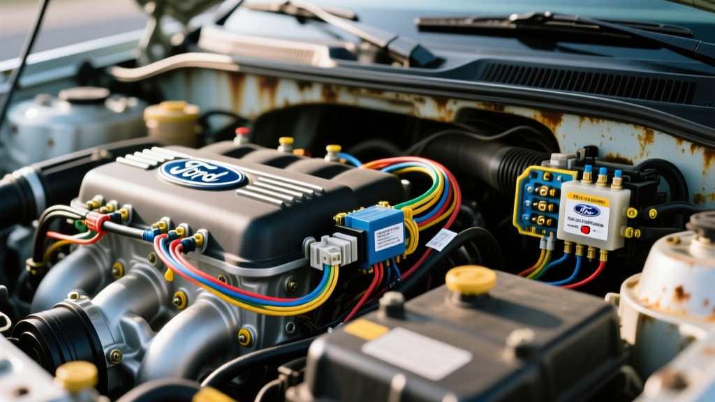
Mastering the Step-by-Step Troubleshooting Flow for the 6.7L Powerstroke
When tackling complex auto repair electrical problems, few platforms test a technician's patience quite like the Ford 6.7L Powerstroke (2011-2019). The sheer volume of control modules—ranging from the Powertrain Control Module (PCM) and Transmission Control Module (TCM) to the Body Control Module (BCM) and Telematics Control Unit (TCU)—creates a dense web of multiplexed data lines and critical ground nodes. A single corroded 14 AWG ground wire or a chafed High-Speed CAN (HS-CAN) bus line can cascade into a dozen seemingly unrelated diagnostic trouble codes (DTCs).
To resolve these issues efficiently, you must abandon the 'parts cannon' approach and adopt a rigorous, step-by-step diagnostic flow. This guide details the exact voltage drop testing sequences, CAN bus isolation trees, and parasitic draw verification steps required to conquer the most notorious Ford Super Duty electrical gremlins.
Phase 1: Ground Circuit Voltage Drop Decision Flow
Over 60% of all iATN-documented driveability and no-crank issues on the 6.7L Powerstroke stem from high-resistance ground circuits. The engine block and chassis must share a near-zero resistance path back to the negative battery post. We focus heavily on Ground G100 and Ground G106.
Step 1: Inspect G100 (Main Engine Block Ground)
- Location: Right-hand battery negative terminal to the upper engine block.
- Specification: 1/0 AWG stranded copper cable with a heavy-duty ring terminal.
- Action: Visually inspect for green copper oxide creeping under the insulation. If present, replace the entire cable assembly; do not attempt to clean and salvage a corroded 1/0 AWG crimp.
Step 2: Perform Cranking Voltage Drop Test on G100
- Set your digital multimeter (DMM) to DC Volts.
- Connect the Red lead directly to the negative battery post (not the clamp, the actual lead post).
- Connect the Black lead to a clean, bare metal spot on the engine block.
- Crank the engine for exactly 5 seconds while monitoring the DMM.
- Decision Node: If the voltage drop exceeds 0.10V DC, the ground path is compromised. Proceed to clean the block mating surface with a brass wire brush and apply dielectric grease, or replace the cable.
Step 3: Verify PCM Ground (G106)
The PCM relies on G106, located on the right-hand strut tower, for critical sensor reference grounds. This circuit typically utilizes a 10 AWG Black/Orange wire.
- Back-probe the PCM connector C1381b, Pin 43 (Sensor Ground).
- Place your DMM Red lead on the battery negative post and the Black lead on the back-probed Pin 43.
- Turn the ignition to 'RUN' (engine off).
- Decision Node: A reading above 0.05V DC indicates a high-resistance fault between the PCM and the chassis ground. This will cause skewed 5V reference signals to the MAP and EBP sensors, leading to false turbocharger over-boost codes.
Phase 2: High-Speed CAN (HS-CAN) Network Isolation
The HS-CAN network operates at 500 kbps and links the PCM, TCM, ABS, and Instrument Panel Cluster (IPC). When diagnosing SAE-standard network communication faults (e.g., U0100 Lost Communication with ECM), follow this isolation flow.
Step 1: Verify Terminating Resistance
The HS-CAN bus requires two 120-ohm terminating resistors (typically housed within the PCM and the IPC) wired in parallel to create a 60-ohm baseline.
- Disconnect the negative battery cable and wait 5 minutes for module capacitors to discharge.
- Set your DMM to Ohms.
- Probe OBD-II DLC Pin 6 (CAN-High) and Pin 14 (CAN-Low).
- Decision Node:
- ~60 Ohms: Network integrity is intact. Fault is likely internal to a specific module.
- ~120 Ohms: One terminating resistor is missing or a CAN wire is broken (open circuit).
- ~0 Ohms: CAN-High and CAN-Low are shorted together, or shorted to ground/power.
Step 2: Active Network Voltage Analysis
Reconnect the battery and turn the ignition to 'RUN'. Use your DMM or a PicoScope to measure the DC bias voltages at the DLC.
| OBD-II Pin | Circuit Name | Typical Ford Wire Color | Expected DC Bias Voltage | Fault Indication |
|---|---|---|---|---|
| Pin 6 | HS-CAN High | White/Blue or Orange/Black | 2.5V to 3.5V | If < 2.5V: Short to ground or CAN-Low |
| Pin 14 | HS-CAN Low | White/Brown or Orange/Brown | 1.5V to 2.5V | If > 2.5V: Short to power or CAN-High |
Step 3: The Module Drop-Off Method
If the network is shorted (0 ohms or biased voltage collapse), do not start cutting wires. Use the 'drop-off' method:
- Monitor DLC Pins 6 and 14 with your scope or DMM.
- Systematically unplug modules on the HS-CAN bus one by one (ABS, TCM, IPC).
- Decision Node: The moment you unplug a module and the network voltage returns to the 2.5V/1.5V baseline, you have found the faulty module causing the internal short. If unplugging all modules yields no change, the short is in the wiring harness itself—check the chassis pass-through grommets near the parking brake pedal, a notorious chafe point on 2015+ F-Series trucks.
Phase 3: BCM Parasitic Draw & Sleep Mode Verification
Late-model Super Duty trucks feature complex infotainment and telematics systems that keep the CAN bus awake long after the key is removed. Misdiagnosing a parasitic draw is one of the most common auto repair electrical problems resulting in unwarranted battery replacements.
Step 1: Prepare for the Sleep Cycle
The BCM and TCU can take up to 45 minutes to enter sleep mode. If you open a door or drop a tool on the floor (triggering the vibration/tilt sensor), the timer resets.
- Use a jumper wire to engage the hood latch switch and all door jamb switches so the vehicle 'thinks' it is closed.
- Remove the OBD-II scan tool. Leaving a scan tool plugged in will continuously ping the DLC, preventing the CAN bus from sleeping.
Step 2: The Inductive Clamp Measurement
Never break the circuit to use a DMM in series for parasitic draw; the inrush current when modules wake up will blow your meter's internal fuse.
- Install a DC Current Clamp (e.g., Fluke i410) around the negative battery cable.
- Zero the clamp and start your logging software or DMM min/max recording.
- Lock the vehicle with the key fob and walk away.
- Decision Node: After 45-60 minutes, the current should drop below 50mA (0.050A). If it remains stuck at 1.5A - 3.0A, a module is failing to sleep. Pull the BCM fuses (typically F22 and F24 in the passenger compartment fuse panel) to verify if the draw drops. If it does, isolate the downstream circuits for a faulty door lock actuator or a stuck CAN-High transceiver inside the radio.
Summary of Acceptable Voltage Drop Limits
Keep this reference chart in your toolbox when diagnosing heavy-duty automotive circuits. These values are derived from Ford Motorcraft Service Procedures and general SAE electrical standards.
| Circuit Type | Wire Gauge (Typical) | Max Allowable Voltage Drop | Test Condition |
|---|---|---|---|
| Main Battery Cables (Cranking) | 1/0 AWG to 2 AWG | 0.50V DC | Engine Cranking |
| Engine Block Grounds | 1/0 AWG | 0.10V DC | Engine Cranking |
| PCM / Sensor Grounds | 14 AWG to 18 AWG | 0.05V DC | Key On, Engine Off |
| Lighting / Accessory 12V Feed | 12 AWG to 16 AWG | 0.20V DC | Under Load (Active) |
Final Expert Advice
Resolving auto repair electrical problems on modern diesel platforms requires a shift from 'testing components' to 'testing the environment the components live in.' A perfectly good fuel injector driver will fail if its 16 AWG Black/Yellow ground wire has 0.8V of voltage drop due to a corroded splice. Trust your voltage drop measurements, respect the CAN bus sleep timers, and always verify the physical integrity of the 1/0 AWG chassis grounds before condemning a $2,000 PCM.