Demystifying Auto Electrical Diagnosis for Beginners
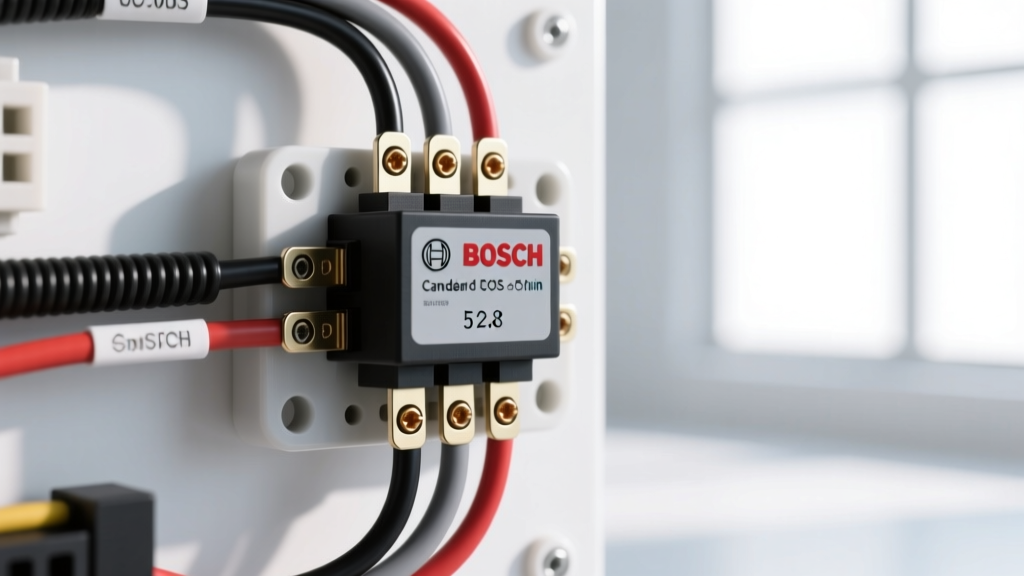
For many novice mechanics and DIY enthusiasts, automotive electrical systems seem like a labyrinth of hidden gremlins and invisible forces. However, mastering auto electrical diagnosis is less about innate genius and more about applying systematic logic to standardized circuits. The absolute best starting point for any beginner is the ubiquitous ISO Mini 5-pin relay, often referred to as the Bosch-style relay. Found in nearly every vehicle manufactured from the late 1990s through the 2010s—including the GM Silverado, Ford F-150, and Honda Accord—this component controls high-amperage loads like cooling fans, fuel pumps, and headlights using a low-amperage switch.
By understanding how to diagnose a single 5-pin relay circuit, you unlock the foundational skills required to troubleshoot 90% of the electrical complaints you will encounter in the bay. This guide breaks down the anatomy, testing procedures, and real-world failure modes of relay circuits, transforming you from a parts-swapper into a true diagnostician.
The Anatomy of an ISO Mini 5-Pin Relay
Before touching a multimeter, you must understand the standardized terminal numbering system defined by the DIN 72552 specification. This German standard ensures that a relay pinout in a 2008 Toyota Tacoma operates on the exact same logical principles as a 2012 Volkswagen Jetta. A standard 5-pin relay contains an electromagnetic coil and a set of internal switch contacts.
| Terminal (Pin) | Function | Typical AWG Size | Common Wire Colors (GM/Ford) |
|---|---|---|---|
| 30 | Common Power Feed (Battery +) | 10 AWG to 12 AWG | Red, Orange, or Pink |
| 85 | Coil Ground / Control Signal | 18 AWG to 20 AWG | Black, Black/White |
| 86 | Coil Power / Control Signal | 18 AWG to 20 AWG | Dark Green, Yellow, Brown |
| 87 | Normally Open (NO) Load Output | 12 AWG to 14 AWG | Blue, Gray, Purple |
| 87a | Normally Closed (NC) Load Output | 12 AWG to 14 AWG | Light Green, Tan (Rarely used) |
When the control module sends power to Pin 86 and ground to Pin 85, the internal coil energizes, creating a magnetic field. This field pulls the internal armature away from Pin 87a and connects Pin 30 to Pin 87, allowing high current to flow to the load (e.g., a 25-amp cooling fan motor).
Essential Tools and Safety Protocols
Proper auto electrical diagnosis requires the right tools. While a traditional incandescent test light is a staple in many toolboxes, it is highly dangerous for modern vehicles. An incandescent test light draws roughly 1.5 to 2.0 amps of current. If you accidentally probe an airbag (SRS) deployment circuit—which utilizes a highly sensitive 2.0-ohm squib—the test light will provide enough current to deploy the airbag in your face.
The Beginner Toolkit:
- Digital Multimeter (DMM): Must have a minimum 10-megohm impedance to prevent back-feeding sensitive ECM/PCM circuits.
- LED Logic Probe: Draws less than 10 milliamps, making it safe for SRS and CAN-bus networks.
- Fused Jumper Wires: Always use a jumper wire with an inline 10-amp or 20-amp fuse. Never bypass a fuse block with raw 12-gauge wire, as a dead short will instantly melt the wiring harness.
Step-by-Step Auto Electrical Diagnosis: The 4-Quadrant Method
When a component fails to operate (e.g., the radiator fan does not spin when the A/C is turned on), beginners often immediately replace the fan motor or the relay. Instead, use the 4-Quadrant Method to isolate the exact point of failure.
Quadrant 1: Verify the Load Power Feed (Terminal 30)
Remove the relay and set your DMM to DC Volts. Place the black lead on a known good chassis ground and the red lead into the female cavity for Terminal 30 in the fuse block. You should read battery voltage (12.2V to 12.6V). If you read 0V, the high-amperage maxi-fuse (usually 30A or 40A) is blown, or the 10 AWG feed wire from the battery is corroded.
Quadrant 2: Test the Control Circuit (Terminals 85 & 86)
The control circuit is the 'brain' side of the relay. With the relay removed and the ignition ON (or A/C commanded ON), probe terminals 85 and 86. One should have 12V (from the PCM or ignition switch), and the other should show continuity to ground. Pro Tip: Pull the relay out and use the Ohms setting on the DMM to measure the resistance across the relay's male pins 85 and 86. A healthy Bosch-style coil will read between 60 and 120 ohms. If it reads 'OL' (Open Line), the internal copper windings are broken. If it reads near 0.0 ohms, the coil is shorted.
Quadrant 3: Verify the Switched Load Path (Terminal 87)
Terminal 87 leads directly to the component. With the relay removed, you can perform a continuity test from the fuse block's Terminal 87 cavity to the positive terminal of the load component. Ensure there are no breaks in the 12 AWG wire. If continuity is good, the wiring to the load is intact.
Quadrant 4: The Ground Path and Voltage Drop Testing
The most misunderstood concept in auto electrical diagnosis is the ground circuit. A component will not run if the ground path has high resistance. To test this, leave the circuit active and perform a voltage drop test. Set your DMM to DC Volts. Place the red lead on the negative battery post and the black lead on the metal casing of the load component (or the ground wire pin). A reading above 0.1V per connection or 0.5V total indicates excessive resistance, usually caused by corrosion or loose crimps.
Real-World Scenario: GM Dual Cooling Fan Failure
Let us apply this to a common failure: the 2003-2006 GM full-size SUV platform (Tahoe, Yukon, Suburban). A frequent complaint is that the A/C blows warm at idle, and the engine runs hot because the primary cooling fan never engages.
The GM system uses a dedicated Fan Control Module containing three ISO mini relays: Fan 1, Fan 2, and a series/parallel control relay. The PCM triggers the Fan 1 relay by providing a ground path on a Dark Green/White (DK GRN/WHT) 18 AWG wire to Terminal 85, while Terminal 86 receives ignition-switched 12V via a Pink (PNK) wire.
The Failure Mode: The 4-pin weather-pack connector leading to the fan motors is located low in the engine bay, exposed to road salt and water. Over time, the female terminals spread and corrode. When the PCM commands the fan ON, the relay clicks (the coil is energized), and 12V leaves Terminal 87 on a Dark Blue (DK BLU) 12 AWG wire. However, due to the corroded weather-pack connector, a massive 4.5V voltage drop occurs before the current reaches the fan motor. The motor receives only 7.5V—insufficient to overcome the rotational inertia of the fan blade. The beginner replaces the relay and the PCM. The expert performs a voltage drop test on the load side, finds the 4.5V drop, and replaces the corroded pigtail connector.
Symptom-Cause-Fix Diagnostic Matrix
| Observed Symptom | Probable Root Cause | Diagnostic Fix / Action |
|---|---|---|
| Relay clicks rapidly (chattering) | Insufficient coil voltage or bad ground | Voltage drop test on Pins 85/86; check for corroded PCM ground splices (e.g., GM G103/G104). |
| Relay gets physically hot to the touch | Internal contact pitting or load drawing excessive amps | Measure amp draw of the component with an inductive amp clamp. A failing fuel pump may draw 22A on a 15A circuit, welding the relay contacts. |
| Component runs with key OFF (Parasitic) | Relay contacts welded closed due to arcing | Pull the relay. If the component stops, replace the relay and inspect the load for a dead short that caused the initial arc. |
| DMM reads 12V at load, but component won't run | High resistance ground or 'Ghost Voltage' | Use a headlight bulb or carbon pile to load-test the circuit. A DMM will read 12V on a single strand of 22 AWG wire, but it cannot carry the 15 amps required by the load. |
Authoritative References and Further Study
To deepen your understanding of automotive relays and circuit testing, refer to these industry-standard resources:
- Littelfuse Automotive Relay Application Guide - An exhaustive breakdown of relay coil specifications, contact materials, and thermal limits.
- Fluke Voltage Drop Testing Guide - The definitive guide on using high-impedance digital multimeters to find hidden resistance in heavy-gauge wiring.
- SAE J1113 Standards for Electromagnetic Compatibility - Essential reading for understanding why modern relays feature internal diodes and resistors to protect sensitive PCM drivers from inductive kickback.
Mastering auto electrical diagnosis is a journey of moving past 'guessing' and embracing measurable data. By anchoring your diagnostic routine to the DIN 72552 relay standard and relying heavily on voltage drop testing, you will solve complex electrical faults faster and more accurately than technicians with decades of experience but poor methodology.