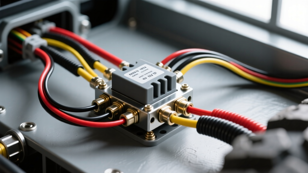
The Anatomy of a Safe Rock Light Wiring Diagram
Rock lights are essential for night wheeling, trail spotting, and camp setup. However, a flawed rock light wiring diagram is one of the leading causes of electrical fires and parasitic battery drains in off-road vehicles. Many DIYers treat a set of 3W or 10W LED pods like simple interior dome lights, routing undersized wires directly through the firewall to a cheap toggle switch. This approach ignores voltage drop, inrush current, and harsh undercarriage environments.
A proper, safety-first rock light wiring diagram utilizes a standard Bosch-style 4-pin 30A relay to isolate the high-current load from the driver’s cabin. Power flows from the battery through an inline fuse to Pin 30 of the relay. Pin 87 feeds the LED pods. The low-current control circuit uses a dash switch or factory Aux bank to trigger Pin 86, while Pin 85 grounds to the chassis. Below, we dissect the six most fatal mistakes made during DIY rock light installations and provide the engineering-backed corrections to keep your rig safe.
6 Fatal Mistakes in DIY Rock Light Installations
Mistake 1: Bypassing the Relay (Direct Battery Switching)
Running 80W of rock lights (approx. 6.6 Amps) directly through a standard 10A dash toggle switch is a recipe for melted plastic. While 6.6A is technically under the switch's 10A rating, LED drivers experience a brief inrush current upon startup that can spike 30% to 50% higher than the steady-state draw. Over time, this thermal cycling degrades the internal contacts of cheap toggle switches, increasing resistance and generating enough heat to melt the switch housing or ignite the dash wiring.
The Fix: Always use a 4-pin automotive relay. According to Hella's automotive relay guide, the relay handles the heavy lifting (up to 30A), while your dash switch only carries the relay coil's negligible 0.15A draw. This eliminates voltage drop in the cabin and prevents switch failure.
Mistake 2: Undersized AWG Wire & Voltage Drop
Most budget rock light kits include spools of flimsy 18 AWG wire. Installers often use this thin wire for the entire 15-foot run from the engine bay to the rear axle. According to SAE J1128 standards for low-tension primary cable, wire gauge must be selected based on both amperage and run length to prevent voltage drop. A 15-foot run of 18 AWG wire carrying 6 Amps will result in a voltage drop of nearly 1.5 Volts. Your rear rock lights will receive only 11.1V, resulting in noticeably dimmer output and premature LED driver failure.
The Fix: Use 12 AWG stranded copper wire for the main trunk line from the battery/relay to the rear of the vehicle. At the rear axle, use a sealed distribution block to split the power to individual pods using 16 AWG wire. This ensures a solid 12.5V+ reaches every pod, even while idling on the alternator.
Mistake 3: Chassis Grounding to Painted Frame Rails
Securing a ground ring terminal over painted steel, powder-coated skid plates, or aluminum control arms with standard flat washers guarantees a high-resistance ground. A poor ground forces the circuit to seek alternative paths, often backfeeding through CAN-bus modules or lighting control units, throwing diagnostic trouble codes (DTCs) and frying sensitive vehicle computers.
The Fix: Use a serrated star washer between the ring terminal and the chassis. The teeth must bite completely through the paint or powder coat to bare metal. For an M8 (8mm) ground bolt, torque the fastener to 15-18 lb-ft. After securing the ground, coat the entire terminal in dielectric grease or fluid film to prevent galvanic corrosion and moisture ingress.
Mistake 4: Missing or Misplaced Inline Fusing
A common and dangerous error is placing the inline fuse near the relay or, worse, near the rock lights themselves. The purpose of the fuse is to protect the wire from the power source to the point of the short. If a 12 AWG wire chafes against the frame rail three feet away from the battery, but the fuse is located fifteen feet away at the relay, the entire length of unfused wire will superheat and catch fire before the fuse blows.
The Fix: Install an ATO or MAXI blade fuse holder within 18 inches of the battery's positive terminal. For an 8-pod, 80W rock light setup drawing ~6.6A, use a 10A fuse. Never oversize the fuse to 'prevent blowing'; the fuse is sized to protect the wire's thermal limit, not the load.
Mistake 5: Routing Through Suspension and Exhaust Pinch Points
Undercarriage wiring faces brutal conditions: mud, water, debris, and extreme suspension articulation. Routing rock light wires parallel to the exhaust without thermal shielding will melt the wire insulation. Furthermore, zip-tying wires tightly to control arms or track bars without accounting for suspension compression and droop will result in the wires snapping or pulling the pods out of their mounts when the suspension cycles.
The Fix: Wrap all undercarriage wiring in split-loom tubing and secure it with Tesa tape (abrasion-resistant fleece tape) to prevent rattling and chafing. Route wires along the factory frame rail wiring harnesses. When crossing to the axle, create a generous 'service loop' (slack) and use a flexible braided sleeve near the exhaust. Always use UV-resistant, stainless-steel backed zip ties or P-clamps with rubber inserts for chassis mounting.
Mistake 6: Overloading Factory Aux Switches (Jeep JL/JT & Bronco)
Modern off-road vehicles like the Jeep Wrangler JL/JT and the Ford Bronco feature upfitter auxiliary switches. In the Jeep JL, Aux 1 and 2 are rated for 40A, but Aux 3 and 4 are only rated for 15A. Some installers wire high-draw rock light kits or combine rock lights with reverse lights directly into Aux 4 without a relay. If the combined inrush and steady-state draw exceeds the BCM (Body Control Module) limit, you risk blowing an irreplaceable internal BCM trace or triggering a hard-lockout of the aux bank.
The Fix: Treat the factory Aux switch strictly as a 12V trigger signal. Run a fused 12V+ wire from the battery to the relay's Pin 30, and use the factory Aux wire (often found under the hood or in the passenger footwell) solely to trigger Pin 86. This draws less than 0.2A from the factory switch, keeping your BCM perfectly safe.
Correct Component Specifications & Wire Sizing Chart
Use the following reference table to size your wiring and protection components based on your specific rock light configuration. Calculations assume a 13.2V charging system and a maximum allowable voltage drop of 3%.
| Configuration | Total Wattage | Amperage Draw | Main Trunk Wire (up to 15 ft) | Branch Wire (per pod) | Recommended Fuse |
|---|---|---|---|---|---|
| 4 Pods (3W each) | 12W | 1.0A | 16 AWG | 18 AWG | 5A ATO |
| 6 Pods (3W each) | 18W | 1.5A | 16 AWG | 18 AWG | 5A ATO |
| 8 Pods (3W each) | 24W | 2.0A | 14 AWG | 18 AWG | 5A or 10A ATO |
| 4 Pods (10W Cree) | 40W | 3.3A | 14 AWG | 16 AWG | 10A ATO |
| 8 Pods (10W Cree) | 80W | 6.6A | 12 AWG | 16 AWG | 10A or 15A ATO |
| 12 Pods (10W Cree) | 120W | 10.0A | 10 AWG | 14 AWG | 15A ATO |
Water Ingress, Termination, and Connector Selection
The undercarriage of an off-road vehicle is essentially a high-pressure car wash. Standard vinyl butt-splices will wick moisture via capillary action, turning your copper wire into green copper oxide within six months. This increases resistance, causes voltage drop, and eventually leads to an open circuit.
According to Painless Performance Wiring guidelines, marine-grade terminations are mandatory for chassis wiring. Use adhesive-lined, dual-wall heat shrink butt connectors. The inner nylon wall melts and seals the wire strands, creating a completely waterproof, IP67-rated bond. For the connection at the rock light pod itself, avoid cheap bullet connectors. Solder and heat-shrink the pigtail directly to the pod if possible, or upgrade to IP68-rated Deutsch DT or AMP Superseal connectors. This allows you to unbolt and replace a damaged pod in the mud without needing wire strippers and a heat gun on the trail.
Troubleshooting: When Rock Lights Flicker or Die
Even with a perfect rock light wiring diagram, environmental abuse can cause failures. Use this diagnostic tree to isolate the issue:
- Symptom: All lights are dead.
- Cause: Blown main fuse, failed relay coil, or bad chassis ground at Pin 85.
- Fix: Test for 12V at Relay Pin 30. If present, jump Pin 30 to Pin 87 with a fused jumper wire. If lights turn on, the issue is in the trigger circuit (switch, Aux bank, or Pin 85 ground).
- Symptom: Rear pods are dim, front pods are bright.
- Cause: Severe voltage drop due to undersized wire, a corroded distribution block, or a daisy-chained ground wire instead of individual grounds.
- Fix: Perform a voltage drop test with a multimeter across the main positive trunk and the main ground trunk while the lights are on. Replace undersized wiring or clean corroded terminals.
- Symptom: Lights flicker violently over bumps.
- Cause: Loose crimp inside a butt-splice, a failing relay contact (internal arcing), or a ground ring terminal that is loose on the chassis.
- Fix: Tug-test all crimps. Retorque the chassis ground bolt and verify the star washer is biting into bare metal.
By respecting the physics of automotive electrical systems and adhering to a proper relay-based rock light wiring diagram, you ensure your lighting system survives the harshest trails without compromising your vehicle's safety or electrical integrity.