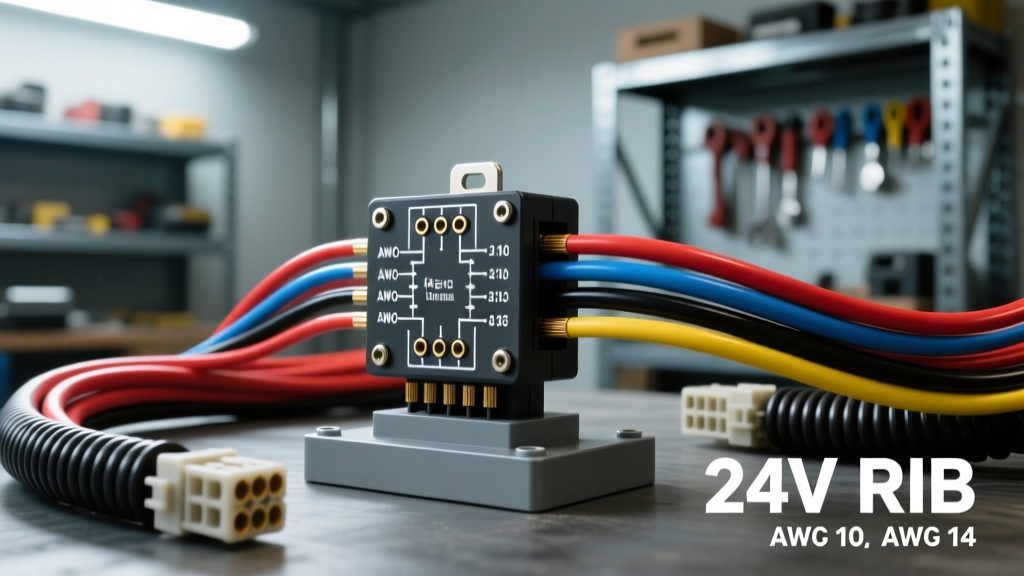
Why Heavy-Duty 24V Systems Require Encapsulated RIB Relays
When upgrading lighting systems on commercial trucks, military platforms, heavy machinery, or marine vessels operating on a 24-volt DC electrical architecture, standard 12V automotive ISO mini relays will fail catastrophically. Applying 24VDC to a 12V relay coil will instantly burn out the winding, leaving your off-road light bars or winch systems dead. While standard 24V Bosch-style relays exist, they often lack the environmental sealing required for harsh undercarriage or marine applications. This is where the RIB (Relay In a Box) becomes the industry standard.
Manufactured primarily by Functional Devices, Inc. (FDI), the RIB relay is a fully encapsulated, potted SPDT (Single Pole Double Throw) relay designed to withstand extreme moisture, vibration, and temperature fluctuations. In this guide, we will break down the exact 24 volt RIB relay wiring diagram, compare the best models for automotive lighting, and provide a heavy-duty installation protocol compliant with SAE J1455 environmental standards for heavy vehicles.
24V RIB Relay Product Comparison Chart
Selecting the correct RIB relay depends on your total lighting load and the need for diagnostic feedback. Below is a comparison of the most common 24VDC RIB configurations used in automotive and marine lighting arrays.
| Model Variant | Coil Voltage | Contact Rating (24VDC) | Encapsulation | Best Application |
|---|---|---|---|---|
| FDI RIB2401 | 24VDC | 10 Amps | Polyurethane Potted | LED light bars, auxiliary reverse lights |
| FDI RIB2402 | 24VDC | 20 Amps | Polyurethane Potted | Halogen fog lights, small winch solenoids |
| FDI RIB24-LED | 24VDC | 10 Amps | Potted w/ Status LED | Marine dash panels, diagnostic troubleshooting |
| FDI RIB2401-D | 24VDC | 10 Amps | Potted w/ Flyback Diode | Switching highly inductive loads (motors, coils) |
For modern LED off-road light bars, which typically draw between 4 to 8 amps on a 24V system, the RIB2401 (10A) is usually sufficient. However, if you are wiring older halogen fog lamps or high-amperage HID ballasts, always step up to the RIB2402 (20A) to prevent contact welding.
Decoding the 24 Volt RIB Relay Wiring Diagram
Unlike standard ISO mini relays that use numbered blade terminals (30, 85, 86, 87, 87a), the RIB series utilizes color-coded wire pigtails encased in a protective housing. Understanding the 24 volt RIB relay wiring diagram is critical, as miswiring the coil or contacts will result in immediate failure.
Coil Wiring (The Control Circuit)
The coil circuit is responsible for creating the electromagnetic field that pulls the internal contactor. In 24VDC RIB models, the coil wires are strictly polarity-sensitive.
- White Wire: Coil Positive (+). Connect this to your 24VDC switched power source (e.g., a dash toggle switch, OEM upfitter switch, or body controller output).
- Black Wire: Coil Negative (-). Connect this to a clean, bare-metal chassis ground or directly to the negative battery terminal.
Expert Note: The coil resistance on a 24VDC RIB is typically around 720 Ohms, drawing roughly 33mA. This incredibly low current draw means you can trigger multiple RIB relays directly from a low-amperage OEM multiplex switch without exceeding the circuit's capacity.
Contact Wiring (The Load Circuit)
The contact circuit handles the heavy current flowing from your batteries to your lighting array. The FDI RIB uses a standard SPDT color code established in industrial automation and adapted for heavy-duty automotive use:
- Yellow Wire: Common (COM). This is your main power input from the 24V battery bank (via a fuse or circuit breaker).
- Blue Wire: Normally Open (NO). This connects to your lighting load. Power flows through this wire only when the coil is energized.
- Orange Wire: Normally Closed (NC). This wire carries power when the relay is at rest. In most automotive lighting applications, the Orange wire is capped off and unused unless you are wiring a dual-function circuit (e.g., daytime running lights that turn off when high beams engage).
Step-by-Step Installation: 24V LED Light Bar Array
Proper installation ensures voltage drop is minimized and the wiring survives the harsh under-hood environment. Follow these steps when executing your 24 volt RIB relay wiring diagram for a 24V LED light bar.
- Calculate Load and Select Wire Gauge: A typical 50-inch 24V LED light bar draws about 6 Amps. According to Littelfuse automotive wiring guidelines, 14 AWG wire is rated for up to 15A, but for runs longer than 10 feet, step up to 12 AWG primary wire to mitigate voltage drop.
- Fuse the Power Feed: Run a 12 AWG wire from the positive battery terminal to an inline ANL or MAXI fuse holder. For a 6A load, use a 10A fuse. Connect the output of the fuse to the Yellow (COM) wire on the RIB relay.
- Wire the Control Circuit: Run 18 AWG wire from your cabin toggle switch to the White (Coil +) wire. Use a heat-shrink butt connector (not a twist-and-tape splice) to seal the connection against moisture. Ground the Black (Coil -) wire using a ring terminal secured to a painted-scraped chassis bolt.
- Connect the Load: Run 12 AWG wire from the Blue (NO) wire to the positive input of your LED light bar. Ground the light bar's negative wire directly to the chassis.
- Seal and Secure: Cap the unused Orange (NC) wire with an adhesive-lined heat shrink cap. Zip-tie the RIB relay to a structural bracket away from exhaust heat sources, ensuring the wire pigtails point downward to prevent water from wicking into the housing.
Real-World Failure Modes and Troubleshooting
Even with a robust encapsulated relay, 24V heavy-duty systems present unique electrical challenges. If your lighting array fails, consult this diagnostic tree:
Symptom: Relay Clicks but Lights Flicker or Dim
Cause: Voltage drop across the contacts or undersized load wiring. While the coil requires only 18VDC to pull in, the contacts may be pitted from previous inductive spikes, increasing internal resistance.
Fix: Measure voltage between the Yellow (COM) and Blue (NO) wires under load. If the voltage drop exceeds 0.2V, replace the RIB relay and verify your 12 AWG wiring is free of corrosion.
Symptom: Relay Fails to Engage (No Click)
Cause: Insufficient coil voltage or a blown control circuit fuse. 24V systems in heavy trucks often suffer from alternator ripple or poor grounding at the upfitter switch panel.
Fix: Use a multimeter to test the voltage between the White and Black wires while the switch is engaged. You must read a minimum of 22VDC. If voltage is low, trace the 18 AWG control wire back to the switch for high-resistance splices.
Symptom: Toggle Switch Melts or Fails Prematurely
Cause: Inductive kickback from the relay coil destroying the switch contacts. While the RIB coil draw is low, the collapse of the magnetic field generates a high-voltage spike.
Fix: Upgrade to the RIB2401-D model, which features an internal flyback diode to suppress voltage spikes, or wire an external 1N4007 diode in reverse parallel across the White and Black coil wires.
By selecting the correct encapsulated model and strictly following the color-coded 24 volt RIB relay wiring diagram, you ensure your auxiliary lighting system operates reliably in the most punishing environments. For further technical specifications, always refer to the Functional Devices RIB datasheets before finalizing your harness design.