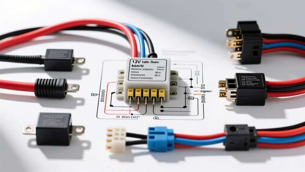
Introduction to Automotive Time Delay Relays
When integrating complex automotive lighting systems—such as retained accessory power for interior courtesy lights, off-road LED light bar sequencing, or headlight off-delay modules—a standard 4-pin or 5-pin Bosch-style relay is insufficient. You need an electronic timer module. Understanding a time delay relay wiring diagram is critical for preventing parasitic battery drain, managing high inrush currents, and ensuring your lighting accessories operate safely after the ignition is turned off.
In this complete walkthrough, we will dissect the wiring architecture of a standard 12V automotive adjustable time delay relay. We will cover DIN 72552 terminal standards, cross-linked polyethylene (TXL/GXL) wire selection, proper crimping methodologies, and specific troubleshooting steps for LED lighting applications.
Core Components and DIN Pinout Configuration
Unlike a standard electromechanical relay that relies purely on a magnetic coil to throw a contact, a time delay relay incorporates an internal RC (resistor-capacitor) timing circuit or a microcontroller. This allows the relay to maintain the load circuit for a predetermined duration after the trigger signal is removed.
Most high-quality automotive timer relays utilize a 5-pin configuration based on standard DIN 72552 terminal numbering. Below is the definitive pinout reference for a standard 5-wire adjustable time delay module.
Standard 5-Pin Timer Relay Module Pinout
| DIN Terminal | Wire Color | Function | Recommended AWG | Connection Point |
|---|---|---|---|---|
| 30 | Red | Constant 12V+ Battery Power (Load Supply) | 10 AWG | Direct to Battery (+) via inline ATO fuse |
| 31 | Black | Chassis Ground | 12 AWG | Clean, bare metal chassis point (ring terminal) |
| 15 | White | Trigger Input (Switched 12V+) | 16 AWG | Ignition switch, door jamb pin, or accessory switch |
| 87 | Blue | Delayed Load Output (+) | 10 AWG | Positive input of lighting accessory / relay coil |
| 87a | Yellow | Potentiometer Adjust / Secondary Trigger | 18 AWG | Adjustment dial or secondary ground trigger (if applicable) |
Complete Time Delay Relay Wiring Diagram Walkthrough
Follow this step-by-step guide to properly wire your time delay relay module. This example focuses on a retained accessory power circuit for a set of aftermarket interior LED courtesy lights, but the principles apply universally to exterior lighting delays.
Step 1: Power and Ground Circuit (AWG & Fusing)
- Route the Constant Power (Terminal 30): Run a 10 AWG GXL (cross-linked) red wire from the positive battery terminal to the relay's Terminal 30. GXL wire is mandatory for engine bay routing due to its 125°C temperature rating and thin insulation profile.
- Install the Primary Fuse: Within 6 inches of the battery positive post, install an inline Littelfuse ATO blade fuse holder. For a standard LED courtesy light setup drawing under 8 amps, use a 15A ATO fuse. This protects the 10 AWG wire from catastrophic thermal events in the event of a dead short.
- Establish the Ground (Terminal 31): Use a 12 AWG black TXL wire. Crimp a 1/4-inch ring terminal onto the wire using a ratcheting crimp tool. Locate a bare metal bolt on the chassis, sand away any paint or powder coating to ensure bare metal contact, and secure the ring terminal. Apply a dab of dielectric grease over the terminal to prevent galvanic corrosion.
Step 2: Trigger Input Wiring
- Identify the Trigger Source: For a door-activated delay, tap into the vehicle's dome light circuit or door jamb switch. If using an ignition-off delay, tap into a 12V+ accessory circuit that goes dead when the key is removed.
- Wire Terminal 15: Run a 16 AWG white wire from your trigger source to Terminal 15. Use a T-tap or, preferably, cut the factory wire and use a 3M dual-wall heat-shrink butt connector to maintain harness integrity. According to SAE J1128 standards, 16 AWG is more than sufficient for the low-current signal required to activate the relay's internal logic gate.
Step 3: Load Output and Lighting Connection
- Connect the Load (Terminal 87): Run a 10 AWG blue wire from Terminal 87 to the positive input of your lighting accessory. If you are driving multiple LED pods or a high-draw light bar, ensure the total continuous amperage does not exceed 80% of the relay's maximum rating (e.g., do not exceed 24A on a 30A rated timer module).
- Ground the Lighting Accessory: Complete the lighting circuit by grounding the negative wire of your LEDs directly to the chassis using a dedicated ground point.
- Adjust the Delay: If your module features a potentiometer on the Yellow (87a) wire or a physical dial on the casing, use a small flathead screwdriver to set the delay time. Test the circuit by opening and closing the door, adjusting the dial until the lights remain illuminated for your desired duration (typically 15 to 30 seconds for courtesy lighting).
Technical Specifications & Wire Sizing Chart
Selecting the correct wire gauge is non-negotiable in automotive electrical systems. Voltage drop over long wire runs can cause the time delay relay's internal microcontroller to reset prematurely or fail to trigger the internal MOSFET. The following chart is based on standard 12V DC automotive applications with a maximum allowable voltage drop of 3%.
| Max Current (Amps) | Wire Length (Under 10 ft) | Wire Length (10 - 20 ft) | Wire Length (Over 20 ft) |
|---|---|---|---|
| 5A - 10A | 16 AWG | 14 AWG | 12 AWG |
| 10A - 20A | 14 AWG | 12 AWG | 10 AWG |
| 20A - 30A | 12 AWG | 10 AWG | 8 AWG |
| 30A - 40A | 10 AWG | 8 AWG | 6 AWG |
Real-World Applications: LED Inrush Current Management
One of the most common failure points when using a time delay relay wiring diagram for modern lighting is ignoring LED inrush current. High-output off-road LED light bars contain large capacitor banks in their internal drivers to smooth out PWM dimming and voltage spikes.
When the time delay relay initially closes the circuit (or when the delay expires and the internal MOSFET engages), these capacitors draw a massive instantaneous spike of current—sometimes 10 to 20 times the steady-state running current. A standard 30A mechanical relay might handle this, but the solid-state switching components inside an electronic time delay module can be instantly vaporized by a 150A inrush spike.
The Expert Fix: If your LED light bar draws more than 15A and has large external heat sinks (indicating heavy driver circuitry), do not run the light bar directly through the time delay relay's Terminal 87. Instead, wire Terminal 87 to trigger the coil of a heavy-duty, contact-rated 40A Bosch-style mechanical relay. Let the time delay module handle the logic, and let the mechanical relay handle the inrush current. This hybrid approach is the gold standard for Bosch automotive relay integrations in the off-road community.
Troubleshooting Common Time Delay Failures
If your lighting system fails to delay, or the relay clicks but the lights do not illuminate, follow this diagnostic decision tree using a digital multimeter (DMM).
- Symptom: Relay clicks immediately, but lights turn off instantly when trigger is removed.
- Cause: Internal timing capacitor failure or incorrect wiring of the trigger wire.
- Fix: Verify that Terminal 15 is receiving a true 12V+ signal. If Terminal 15 is wired to a ground-switched circuit (common in modern CANbus vehicles where the BCM switches the ground), you must use a relay to invert the signal, or purchase a specific ground-trigger time delay module.
- Symptom: Relay does not click, no lights, but fuse is intact.
- Cause: High resistance on the ground circuit (Terminal 31).
- Fix: Set your DMM to Ohms (Ω). Measure resistance between Terminal 31 and the negative battery post. It should read less than 0.5 Ω. If it reads higher, clean your chassis ground point and re-crimp the ring terminal.
- Symptom: Lights flicker rapidly as the delay timer counts down.
- Cause: Voltage drop across the internal MOSFET or failing solid-state switch inside the timer module.
- Fix: Set your DMM to DC Volts. Measure voltage between Terminal 30 and Terminal 87 while the lights are flickering. If you read a voltage drop greater than 0.5V across the relay, the internal switching component is failing due to thermal overload. Replace the module with a higher amperage rated unit or implement the hybrid mechanical relay fix mentioned above.
Conclusion
Executing a proper time delay relay wiring diagram requires more than just connecting colored wires; it demands an understanding of DIN standards, SAE wire gauging, and the specific electrical characteristics of modern LED lighting. By utilizing TXL/GXL wiring, properly fusing the constant 12V supply, and accounting for LED inrush currents, you ensure a robust, fire-safe, and highly reliable lighting system that enhances both the functionality and aesthetics of your vehicle.