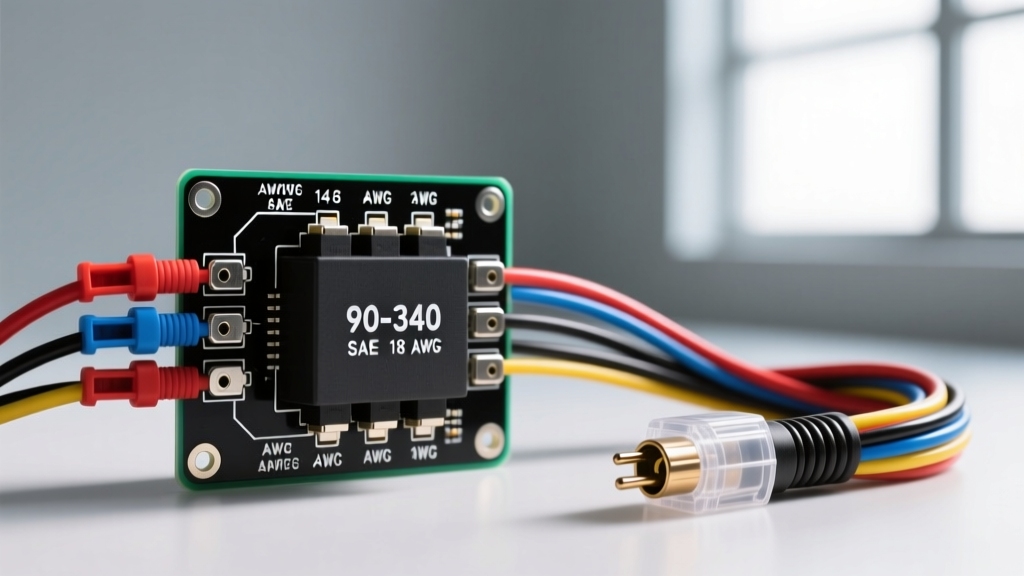
Understanding the 90 340 Relay Wiring Diagram
When upgrading your vehicle with high-draw auxiliary lighting, LED light bars, or heavy-duty fog lamps, routing power directly through the factory switch is a guaranteed way to melt your OEM wiring harness. The 90-340 series relay—a robust 5-pin, 12V, 40A SPDT (Single Pole Double Throw) ISO mini relay—is the industry standard for isolating high-amperage lighting circuits from low-amperage trigger switches. This practical guide breaks down the exact 90 340 relay wiring diagram, providing the AWG specifications, crimping protocols, and SAE safety standards required for a professional-grade installation.
90 340 Relay Pinout and AWG Specifications
Before cutting any wire, you must understand the ISO standard pin configuration. The 90-340 relay utilizes standard 0.250-inch (6.3mm) spade terminals. Below is the definitive pinout matrix for auxiliary lighting applications.
| Pin Number | Terminal Type | Circuit Function | Recommended AWG | Standard Wire Color |
|---|---|---|---|---|
| 30 | Male Spade | Common (Battery Power In) | 10 AWG | Red |
| 87 | Male Spade | Normally Open (Load/Accessory Out) | 12 AWG | Yellow |
| 87a | Male Spade | Normally Closed (Unused in Lighting) | N/A | Capped/Sealed |
| 86 | Male Spade | Coil Power (Switch Trigger In) | 16 AWG | White |
| 85 | Male Spade | Coil Ground (Chassis Ground) | 16 AWG | Black |
Note: Pin 87a is the Normally Closed circuit. In a standard light bar or fog light installation, this pin remains unconnected. Leaving it exposed in an engine bay invites moisture and short circuits; always cap it with adhesive-lined heat shrink.
Required Tools and Materials
Do not rely on cheap crimp pliers for under-hood wiring. Vibration and thermal cycling will destroy poorly crimped connections. Assemble the following before beginning:
- Wire: SAE J1128 compliant cross-linked polyethylene (XLPE) primary wire.
- Terminals: Aptiv Metri-Pack 280 series or high-quality nylon-insulated spade connectors.
- Crimper: Ratcheting terminal crimper (e.g., Titan 11610 or equivalent).
- Sealing: 3:1 shrink ratio, dual-wall adhesive-lined heat shrink tubing.
- Fuse: ATO/ATC blade fuse and inline weatherproof holder.
- Hardware: Stainless steel ring terminals, star washers, and zip ties with UV-resistant ratings.
Step-by-Step Installation Guide
Step 1: The Main Power Circuit (Pin 30)
The highest current flows through Pin 30. Cut a length of 10 AWG red wire to reach from the positive battery terminal to the relay mounting location, plus an extra 12 inches for service loops. Critical Safety Rule: Per SAE J1284 standards for blade fuses, the inline fuse holder must be installed within 18 inches of the battery positive terminal. If the wire chafes against the chassis before the fuse, you risk an unprotected dead-short and a vehicle fire. Strip the wire, crimp a ring terminal using your ratcheting crimper, seal with heat shrink, and secure to the battery post.
Step 2: Routing the Load Circuit (Pin 87)
Pin 87 delivers power to your auxiliary lights. Use 12 AWG yellow wire for this run. If your light bar draws under 15A, 12 AWG is more than sufficient to prevent voltage drop over a standard 10-foot run. Route this wire through the engine bay, avoiding exhaust manifolds and steering shafts. When passing through the firewall or radiator core support, always use a rubber grommet to prevent insulation abrasion. Connect the female spade terminal to Pin 87 on the relay harness.
Step 3: Establishing the Trigger Circuit (Pin 86)
Pin 86 activates the relay's internal electromagnet. This circuit requires very little current (typically under 150mA), so 16 AWG wire is perfect. You have two options for triggering the 90-340 relay:
- OEM Fog Light Tap: Use a POSI-TAP connector to tap into the positive wire of your factory fog light circuit. This allows your OEM stalk switch to control the relay.
- Dedicated Switch: Run the wire through the firewall to an aftermarket toggle switch inside the cabin. The switch must be fed by an ignition-switched 12V source (e.g., the radio or accessory fuse tap) to prevent parasitic battery drain when the vehicle is off.
Step 4: Grounding the Coil (Pin 85)
The relay coil requires a solid ground to complete the electromagnetic circuit. Cut a short 16 AWG black wire and attach it to Pin 85. Route the other end to a clean, bare metal point on the chassis or engine block. Pro Tip: Use a star washer to bite through paint and rust, ensuring a zero-resistance connection to the vehicle's negative ground plane. Coat the finished ground point with dielectric grease to prevent galvanic corrosion.
Calculating Fuse Size: Relay Rating vs. Circuit Load
A common and dangerous mistake among novices is placing a 40A fuse on Pin 30 simply because the 90-340 relay is rated for 40 Amps. The fuse protects the wire and the load, not the relay. If you are installing a 120W LED light bar, the current draw is calculated as:
Current (Amps) = Watts / Volts
120W / 12.6V = 9.52 Amps
Applying the 125% continuous load safety margin recommended by the SAE J554 Electric Fog Lamps standard, your maximum protected current should be roughly 12 Amps. Therefore, you should install a 15A ATO blade fuse in the Pin 30 inline holder. Using a 40A fuse on a 120W light bar means the wire will melt and catch fire long before the fuse blows during a short circuit event.
Real-World Troubleshooting Matrix
Even with a perfect 90 340 relay wiring diagram, environmental factors and installation errors can cause failures. Use this diagnostic tree to resolve common issues.
| Symptom | Probable Cause | Diagnostic Fix |
|---|---|---|
| Relay clicks rapidly (chatter) but lights flicker or stay off. | High resistance on Pin 85 ground or low voltage at Pin 86 trigger. | Check chassis ground with a multimeter. Clean contact point and verify trigger wire is not suffering from voltage drop. |
| Relay gets excessively hot to the touch after 10 minutes. | Overloaded circuit (drawing near 40A) or poor connection at Pin 30/87 causing arcing. | Measure actual amperage draw with an inline clamp meter. Inspect spade terminals for looseness; recrimp if necessary. |
| Auxiliary lights remain on after the ignition is turned off. | Pin 86 trigger wire is wired to a constant 12V battery source instead of a switched source. | Move the trigger tap to an ignition-controlled circuit (e.g., wiper motor or accessory fuse). |
| Lights do not turn on; relay does not click. | Blown inline fuse or broken coil winding inside the 90-340 relay. | Test fuse with a multimeter for continuity. Apply direct 12V and ground to pins 86 and 85 to test the coil independently. |
Crimping vs. Soldering in Automotive Environments
While soldering is often praised in household electronics, it is generally discouraged for under-hood automotive wiring by major manufacturers and the SAE J1128 Low Tension Primary Cable standard. Solder creates a rigid point in the wire harness. The constant vibration of a vehicle engine and chassis will cause the wire to fatigue and snap exactly at the edge of the solder joint. A properly executed mechanical crimp using a ratcheting tool creates a cold-weld, gas-tight connection that allows the wire to remain flexible and withstand harsh thermal cycling. Always follow your crimp with adhesive-lined heat shrink to seal out engine bay moisture and prevent copper oxidation.
Final System Verification
Before sealing up your wire loom and zip-tying the harness, perform a final operational check. Turn on the vehicle, activate the trigger switch, and verify the auxiliary lights illuminate instantly without relay chatter. Use a digital multimeter to measure the voltage at the light bar's input connector while the lights are on. You should read no less than 13.2V (with the engine running). If you read significantly lower, you have excessive resistance in the Pin 30 or Pin 87 circuits, requiring an upgrade to a thicker AWG wire or a thorough inspection of your crimped terminals.