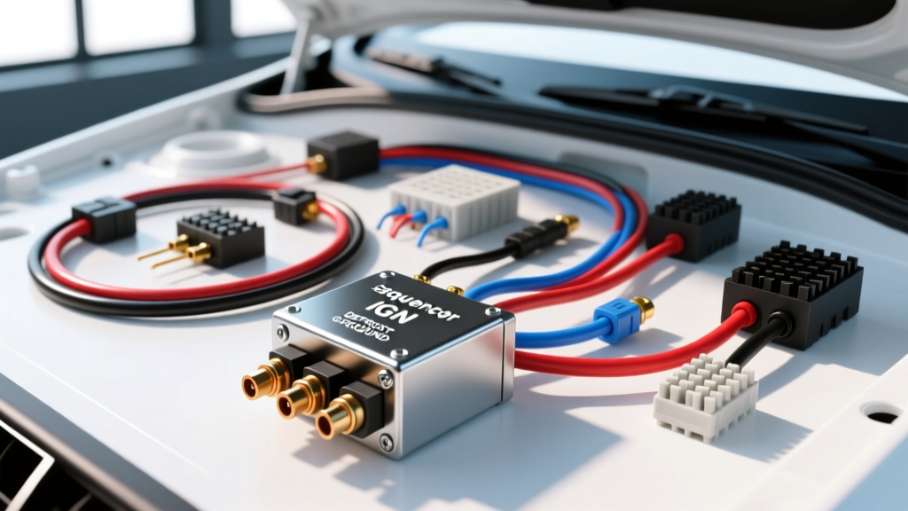
Understanding the Heat Sequencer Relay Wiring Diagram
When outfitting heavy-duty trucks, RVs, or custom off-road vehicles with high-amperage auxiliary rear defroster grids or heated mirror arrays, turning all heating elements on simultaneously creates a massive inrush current. This sudden electrical demand can cause severe voltage drops, dim lighting systems, and alternator overload. The solution lies in a properly executed heat sequencer relay wiring diagram, which staggers the activation of multiple high-amp heating circuits over a period of seconds.
In this practical installation guide, we will break down how to wire a solid-state heat sequencer module paired with heavy-duty ISO mini relays to safely manage auxiliary HVAC heating elements. We will cover specific wire gauges, connector types, and pin configurations required for a reliable, vibration-resistant installation that meets automotive electrical standards.
The Core Components of a Sequencer Circuit
Unlike a standard single-relay lighting circuit, a heat sequencer system requires a timer module that acts as the brain, triggering multiple slave relays in a delayed sequence. According to the Littelfuse Automotive Relay Guide, utilizing multiple 40A or 50A ISO mini relays is preferred over a single massive continuous-duty solenoid for defroster grids, as it allows for isolated circuit protection and easier troubleshooting.
System Architecture
- Sequencer Timer Module: A 12V solid-state timer with one trigger input and multiple delayed 12V+ outputs (e.g., 0s, 2s, 4s delays).
- Slave Relays: Standard 4-pin or 5-pin Bosch-style ISO mini relays (rated for minimum 40A continuous).
- Inline Fuses: ATO/ATC blade fuses or Mega fuses located within 18 inches of the battery positive terminal.
- Connectors: Sealed Aptiv Metri-Pack 280 series or Deutsch DT connectors for all under-hood and exterior connections to prevent moisture ingress.
Technical Specifications & Wire Sizing Chart
Adhering to the SAE J1128 Low Tension Primary Cable Standard is critical when selecting wire for high-heat environments like engine bays or behind interior dash panels. Heating elements draw continuous, high-amperage loads, meaning voltage drop over long wire runs (common in RVs and crew-cab trucks) must be calculated.
| Circuit Type | Max Amperage | Recommended AWG | Wire Type | Fuse Rating |
|---|---|---|---|---|
| Main Battery Feed (Sequencer) | 120A (Total) | 2 AWG | SGT Battery Cable | 150A Mega Fuse |
| Sequencer to Relay Coil (Control) | 2A per channel | 16 AWG | GXL Cross-linked | 5A ATO |
| Relay Load (Pin 30 to 87) | 30A per grid | 10 AWG | GXL Cross-linked | 35A ATO |
| Ground Returns | 30A per grid | 10 AWG | GXL Cross-linked | N/A (Ring Terminal) |
Step-by-Step Installation Guide
Step 1: Mounting the Sequencer and Relays
Locate a dry, well-ventilated area in the engine bay or behind the kick panel. Mount the sequencer module using stainless steel hardware. If using a relay harness block, ensure the block is rated for the cumulative amperage of your heating grids. Apply a thin layer of dielectric grease to the relay blades before inserting them into the sockets to prevent galvanic corrosion.
Step 2: Wiring the Control Circuit (Low Amp)
The control circuit triggers the relays without carrying the heavy heating load.
- Switch Input: Run 16 AWG wire from your dashboard defroster switch to the 'Trigger In' terminal on the sequencer module.
- Sequencer Outputs: Run 16 AWG wire from each delayed output on the sequencer to Pin 86 on each respective ISO mini relay.
- Relay Grounds: Wire Pin 85 on all relays to a clean, bare-metal chassis ground using 16 AWG wire and a #10 ring terminal. Scrape away any paint or powder coating at the grounding point and secure with a star washer.
Step 3: Wiring the Load Circuit (High Amp)
This is where the heavy current flows to the heating elements.
- Main Power Feed: Run 2 AWG wire from the battery positive terminal, through a 150A Mega fuse, to a heavy-duty distribution busbar mounted near the relays.
- Relay Input (Pin 30): Run 10 AWG wire from the busbar to Pin 30 on each relay. Install a 35A ATO inline fuse on each 10 AWG run, positioned as close to the busbar as possible.
- Relay Output (Pin 87): Run 10 AWG wire from Pin 87 on each relay to the positive terminal of your auxiliary defroster grid or heated mirror element.
- Element Grounding: Ground the negative side of the heating elements directly to the vehicle chassis using 10 AWG wire. Do not daisy-chain the grounds; each heating grid must have its own dedicated ground path to prevent ground-loop voltage drops.
Real-World Troubleshooting & Failure Modes
Even with a perfect heat sequencer relay wiring diagram on paper, real-world installations encounter issues. Use this diagnostic tree to isolate faults:
Symptom: Sequencer clicks, but defroster grids do not heat up.
- Cause 1: Blown inline ATO fuse on Pin 30. Fix: Check for a short to ground in the 10 AWG load wire between the relay and the heating element.
- Cause 2: High resistance at Pin 87 terminal. Fix: Perform a voltage drop test across the relay socket. If voltage drop exceeds 0.2V under load, replace the relay socket; the internal brass contacts are likely oxidized or loose.
Symptom: Grids heat up, but dashboard lights dim severely upon activation.
- Cause 1: Sequencer delay timing is too short, causing overlapping inrush currents. Fix: Adjust the potentiometer on the sequencer module to increase the delay between channels to a minimum of 3 seconds.
- Cause 2: Undersized main battery feed wire. Fix: Verify the 2 AWG main feed is not exceeding 15 feet in total length. If longer, upgrade to 1/0 AWG welding cable to mitigate voltage drop.
Symptom: Relay coil gets excessively hot and melts the plastic socket.
- Cause 1: Using a 5-pin relay with the 87a (Normally Closed) pin populated in a high-amp harness. Fix: Never run high-amp heating loads through Pin 87a. The internal copper trace for 87a is not designed for continuous 40A loads. Use strictly 4-pin relays or leave Pin 87a empty.
Final Inspection and Testing
Once all connections are crimped—never soldered under the hood due to vibration-induced fatigue—use a multimeter to verify continuity before applying main battery power. Activate the dashboard switch and use an infrared thermometer to monitor the defroster grids. You should observe each grid section heating up sequentially, confirming that your heat sequencer relay wiring diagram has been executed correctly and your vehicle's electrical system remains protected from catastrophic overload.