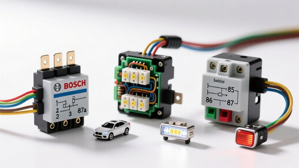
Why Relay Selection Dictates Your Wiring Diagram
When planning an automotive lighting upgrade, searching for a generic relay wiring diagram often leads to frustrating results. You might find a basic sketch for a standard 4-pin Bosch relay, only to realize it lacks the circuitry for daytime running light (DRL) cutoffs or PWM dimming compatibility. The truth is that the correct relay wiring diagram depends entirely on the switching logic your specific lighting application demands. Selecting the wrong relay type not only results in a non-functional circuit but can also trigger CAN-bus faults, melt undersized wiring, or destroy sensitive ECU driver modules.
According to the SAE J1823 standard for automotive relays, understanding terminal designations, coil suppression requirements, and continuous current ratings is mandatory for safe electrical integration. Below, we compare the three primary relay architectures used in aftermarket lighting—Standard 4-Pin SPST, 5-Pin SPDT Changeover, and Solid-State (SSR)—and break down the exact relay wiring diagram logic for each.
The Standard 4-Pin SPST Relay (Bosch Style)
The Single Pole Single Throw (SPST) 4-pin relay is the workhorse of automotive lighting. It operates as a simple remote-controlled switch, utilizing a low-current electromagnetic coil to close a high-current contact. If you are wiring a standalone LED light bar, auxiliary fog lights, or a headlight relay upgrade on a pre-CAN-bus vehicle, this is the relay wiring diagram you need.
DIN 72552 Pinout & Diagram Logic
Following the DIN 72552 terminal designation standard, the 4-pin relay utilizes the following layout:
- Pin 30 (Common / Power In): Connected directly to the battery positive terminal via a main inline fuse. Use 10 AWG wire for 30A loads or 12 AWG for 20A loads.
- Pin 87 (Normally Open / Load Out): Connects to the positive lead of your lighting fixture. When the coil is energized, Pin 30 bridges to Pin 87.
- Pin 85 (Coil Ground): Connects to a clean chassis ground or directly to the battery negative. Use 16 AWG wire.
- Pin 86 (Coil Power / Trigger): Connects to your switched 12V source (e.g., high-beam wire, upfitter switch, or ignition source). Use 18 AWG wire.
Expert Note: If your trigger source originates from a modern vehicle's ECU or BCM (Body Control Module), you must use a relay with an internal suppression resistor or diode across pins 85 and 86. Without this, the inductive flyback voltage spike generated when the coil de-energizes can exceed 100V, instantly frying the ECU's low-side driver transistor.
The 5-Pin SPDT Changeover Relay
The Single Pole Double Throw (SPDT) 5-pin relay introduces a critical fifth terminal: Pin 87a. This pin is "Normally Closed" (NC). In its resting state, Pin 30 is bridged to Pin 87a. When the coil is energized, the bridge breaks from 87a and connects to Pin 87. This specific relay wiring diagram is essential for applications requiring "either/or" lighting logic.
Best Applications: DRL Cutoffs and Headlight Dimming
Imagine you are wiring a set of auxiliary 55W H11 halogen fog lights, but you want them to act as your Daytime Running Lights. When you turn on your main low-beam headlights, the DRLs must shut off to prevent glare and circuit overload.
In this relay wiring diagram configuration:
- Pin 30: Receives switched 12V from the ignition.
- Pin 87a: Routes power to the fog lights (acting as DRLs when the relay is at rest).
- Pin 87: Left unconnected or routed to a high-beam indicator.
- Pin 86: Triggered by the low-beam headlight circuit.
When the low beams turn on, Pin 86 receives 12V, energizing the coil. The internal switch pulls away from Pin 87a (cutting power to the fog lights) and moves to Pin 87. This elegant changeover logic eliminates the need for complex diode steering networks in the wiring harness.
Solid-State Relays (SSR) for High-Current LED Arrays
Mechanical relays rely on physical metal contacts that arc, pit, and eventually weld together under high inrush currents. Furthermore, they cannot handle Pulse Width Modulation (PWM) dimming. If you attempt to use a standard mechanical relay wiring diagram for an LED light bar equipped with a PWM dimmer (which switches power at 200Hz to 500Hz), the relay will chatter violently and fail within minutes.
For PWM-compatible lighting, EMI-sensitive environments, or high-vibration applications (like Baja racing trucks), you must select a Solid-State Relay (SSR). SSRs use MOSFET transistors to switch the load electronically with zero moving parts.
How SSR Wiring Diagrams Differ
An automotive SSR wiring diagram looks similar to a 4-pin mechanical relay but operates differently on the trigger side. Because there is no electromagnetic coil, there is no flyback voltage spike, making SSRs inherently safe for direct ECU triggering. However, SSRs often require a dedicated ground for the internal logic board. Many high-quality automotive SSRs feature 5 pins: Power In (30), Load Out (87), Logic Ground, Trigger Positive, and Trigger Negative. Always verify the manufacturer's specific SSR relay wiring diagram, as pinouts are not universally standardized like DIN mechanical relays.
Comparison Matrix: Relay Types vs. Lighting Loads
| Relay Type | PIN Standard | Max Continuous Load | Coil Draw | Ideal Lighting Application | DIMMING / PWM |
|---|---|---|---|---|---|
| Standard 4-Pin SPST | DIN 72552 | 30A - 40A | ~150mA | Light Bars, Off-Road Spotlights | No (Mechanical Chatter) |
| 5-Pin SPDT Changeover | DIN 72552 + 87a | 30A | ~150mA | DRL Cutoffs, Fog Light Logic | No |
| Solid-State (MOSFET) | Varies by Mfg. | 50A - 120A | < 10mA | PWM Dimmable LED Arrays, CAN-bus | Yes (High Frequency) |
Wiring Harness & Connector Selection
A flawless relay wiring diagram is useless if executed with poor materials. The most common point of failure in aftermarket lighting is not the relay itself, but the connector interfacing with it. Standard 1/4-inch stamped steel spade terminals are prone to oxidation, vibration loosening, and thermal expansion under sustained 20A+ loads.
For professional-grade lighting installations, discard the cheap pigtail sockets included with most relay kits. Instead, crimp your wires using Metri-Pack 280 series or Weather-Pack terminals, and house them in a sealed relay block. According to TE Connectivity's automotive relay guidelines, maintaining low contact resistance at the terminal interface is critical to preventing voltage drop and localized melting in high-ambient-temperature engine bays. Always use adhesive-lined heat shrink and marine-grade tinned copper wire for any harness routed near the radiator or exposed frame rails.
Real-World Failure Modes & Troubleshooting
When your lighting upgrade fails to operate, use this diagnostic decision tree before replacing components:
- Symptom: Lights flicker randomly while driving.
Cause: Vibration is causing a poor ground on Pin 85, or the trigger source (Pin 86) is experiencing voltage fluctuations.
Fix: Bypass the chassis ground and run a dedicated 16 AWG ground wire directly to the battery negative. Check trigger wire for chafing. - Symptom: Lights stay on after the switch is turned off.
Cause: The internal contacts of Pin 30 and 87 have micro-welded together due to arcing from an inrush current exceeding the relay's rating.
Fix: Replace the relay with a higher amperage unit or an SSR. Add a soft-start module to the LED driver if inrush current is the culprit. - Symptom: ECU throws a "Bulb Out" code on the dash.
Cause: Modern BCMs monitor circuit current draw. A relay coil drawing only 150mA mimics a blown bulb to the ECU.
Fix: Install a CAN-bus load resistor (typically 6-ohm, 50W) in parallel with the trigger circuit, or use a CAN-bus compatible SSR that mimics the load profile of a halogen bulb.
Mastering the correct relay wiring diagram for your specific application ensures maximum lumen output, protects your vehicle's sensitive multiplexed wiring systems, and guarantees your lighting operates flawlessly in the harshest environments.