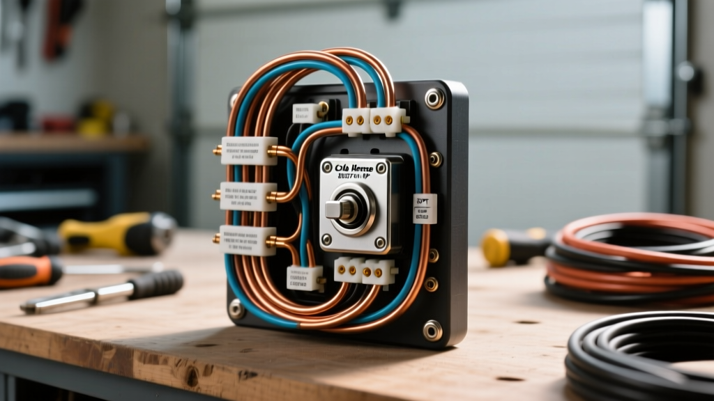
Understanding the Cole Hersee 56327-01-BP Architecture
The Cole Hersee 56327-01-BP is a heavy-duty, Single Pole Single Throw (SPST) rocker switch engineered for demanding custom automotive, marine, and off-road electrical installations. Frequently deployed to control auxiliary lighting arrays, air compressors, and winch solenoids, this switch is prized for its robust internal copper contactor and ergonomic rocker actuator. However, like any electromechanical component subjected to high-amperage DC loads and harsh environmental conditions, it is susceptible to specific failure modes. Carbon tracking, terminal oxidation, and inductive arcing can compromise the circuit. This guide provides an expert-level, step-by-step troubleshooting flow to isolate and resolve faults within custom wiring harnesses utilizing the 56327-01-BP.
Before initiating diagnostic procedures, it is critical to verify that the foundational installation parameters align with the manufacturer specifications and SAE J1128 standards for low-tension primary automotive cable. Improper wire gauge selection or inadequate crimp terminations are the leading causes of premature switch failure, often misdiagnosed as internal switch defects.
Technical Specifications and Installation Parameters
| Parameter | Specification |
|---|---|
| Switch Type | SPST (Single Pole, Single Throw), 2-Terminal |
| Current Rating | 20A at 12V DC (Resistive Load) |
| Terminal Type | 0.250 in. (6.35mm) Male Quick-Connect Blades |
| Panel Cutout Dimensions | 1.45 in. x 0.83 in. (36.8mm x 21.1mm) |
| Recommended Wire Gauge | 12 AWG TXL or GXL (Cross-Linked Polyethylene) |
| Dielectric Strength | Tested to withstand 1000V AC for 1 minute |
| Operating Temperature | -40°F to 185°F (-40°C to 85°C) |
Symptom-Cause-Fix Decision Tree
Use the following decision tree to rapidly isolate the root cause of your circuit malfunction. This flow assumes the power source (battery/alternator) is verified healthy and the ground circuit to the load has been confirmed intact.
Symptom 1: Switch Actuates (Clicks) but Load Fails to Engage
- Cause A: Blown Inline Fuse or Tripped Circuit Breaker. The switch is functioning, but upstream protection has opened due to a short or overload. Fix: Inspect the MAXI or ATO fuse located within 18 inches of the power source. Replace with the correct amperage rating; never up-size the fuse.
- Cause B: Internal Contactor Failure. The mechanical rocker engages the plastic actuator, but the internal copper bridge has fractured or lost spring tension. Fix: Perform a bench continuity test (Phase 2 below). If open, replace the switch.
- Cause C: High Resistance at Quick-Connect Terminals. Vibration has loosened the female quick-disconnect crimps on the 0.250 in. male blades, preventing current flow. Fix: Remove terminals, squeeze the female brass inserts with needle-nose pliers to restore tension, and re-crimp using a ratcheting tool.
Symptom 2: Switch Housing is Hot to the Touch
- Cause A: Continuous Overloading. The connected load exceeds the 20A DC resistive rating. Motors and compressors draw high inrush currents that pit the internal contacts, generating excessive heat. Fix: Integrate a heavy-duty automotive relay (e.g., 40A Bosch-style) so the switch only handles the low-amperage relay coil circuit (typically under 2A).
- Cause B: Carbon Tracking from Inductive Arcing. Switching off inductive loads without a flyback diode causes voltage spikes that arc across the internal contacts, building up resistive carbon deposits. Fix: Replace the switch and install a flyback diode across the load terminals, or utilize a relay.
Symptom 3: Intermittent Operation Over Bumps
- Cause A: Wire Fatigue at the Crimp Joint. Standard PVC wire has stiffened and fractured internally where it meets the terminal barrel due to engine bay vibration. Fix: Cut back the wire to fresh copper and re-terminate using adhesive-lined marine heat shrink.
- Cause B: Inadequate Panel Retention. The switch is vibrating within the 1.45 in. x 0.83 in. cutout, causing the terminals to short against the metal dashboard or chassis. Fix: Ensure the panel thickness is within the switch's specified grip range (typically 0.062 in. to 0.125 in.) and apply a silicone bead around the bezel if necessary.
Step-by-Step Multimeter Diagnostic Flow
To definitively diagnose the Cole Hersee 56327-01-BP, you must utilize a Digital Multimeter (DMM). Relying on test lights is insufficient, as test lights do not reveal voltage drop or high-resistance faults under load.
Phase 1: Voltage Drop Testing (Live Circuit Under Load)
Voltage drop testing identifies hidden resistance without disconnecting the harness. A healthy SPST switch should exhibit virtually zero voltage drop across its terminals.
- Prepare the DMM: Set your multimeter to DC Voltage (20V scale).
- Energize the Circuit: Turn the rocker switch to the ON position. Ensure the load (e.g., auxiliary lights) is attempting to draw current.
- Probe the Input Terminal: Place the black DMM probe on a known good chassis ground. Place the red probe on the switch's input terminal (the wire coming from the fused battery source). You should read full system voltage (12.4V to 14.2V). If lower, the fault is upstream of the switch.
- Probe the Output Terminal: Move the red probe to the switch's output terminal (the wire leading to the load). The voltage reading should be identical to the input terminal.
- Calculate the Drop: Alternatively, place the red probe on the input terminal and the black probe directly on the output terminal. Diagnostic Threshold: A reading greater than 0.2V indicates internal contactor resistance or terminal corrosion. The switch must be replaced.
Phase 2: Continuity and Resistance Testing (Bench Test)
If the live circuit test is inconclusive or the switch has been removed from the vehicle, perform a bench test to evaluate the mechanical integrity of the internal copper bridge.
- Isolate the Component: Disconnect both wires from the 0.250 in. male quick-connect blades. Ensure the switch is completely removed from any live circuit.
- Set DMM to Ohms: Select the lowest resistance setting (usually 200 Ohms) or the Continuity tone setting.
- Zero the Meter: Touch the red and black probes together. Note the baseline resistance of your test leads (usually 0.1 to 0.3 Ohms).
- Test the OFF State: Place probes on the two male blades. Ensure the rocker is in the OFF position. The DMM must read 'OL' (Open Loop) or infinite resistance. Any reading here indicates a melted internal housing or shorted carbon tracking.
- Test the ON State: Actuate the rocker to the ON position. The DMM should read less than 0.5 Ohms (subtracting your test lead baseline). If the reading fluctuates or exceeds 1.0 Ohm, the internal spring tension has failed, or the contact pads are severely pitted.
Inductive Load Failures and Relay Integration
A critical mistake in custom off-road and marine wiring is using a 20A SPST rocker switch to directly control inductive loads like winch solenoids, air horns, or high-amperage fuel pumps. According to Littelfuse commercial vehicle engineering guidelines, the 20A rating of the 56327-01-BP applies strictly to resistive loads (like incandescent bulbs or heating elements). Inductive loads generate massive inrush currents upon startup and severe voltage spikes upon shutdown.
When you open the SPST contacts to turn off a winch solenoid, the collapsing magnetic field induces a voltage spike that can exceed 100V. This spike arcs across the separating copper contacts inside the rocker switch, vaporizing microscopic amounts of metal and depositing insulating carbon. Over time, this causes the 'hot switch' symptom and eventual open-circuit failure.
The Expert Fix: Always use the Cole Hersee 56327-01-BP to trigger the coil circuit (Terminals 85 and 86) of a heavy-duty relay. The switch will then only carry the 1A to 2A required to energize the relay coil, entirely eliminating internal arcing and extending the switch's lifespan indefinitely. Refer to Painless Performance wiring manuals for standard 5-pin relay integration diagrams.
Proper Termination and Weatherproofing
The 0.250 in. quick-connect terminals on the 56327-01-BP require precise crimping to prevent voltage drop and moisture ingress. Standard vinyl-insulated crimps are insufficient for engine bay or marine environments.
- Wire Selection: Use 12 AWG GXL or TXL wire. The cross-linked polyethylene insulation has a much higher melting point than standard PVC, allowing it to withstand the heat generated if the switch operates near its 20A maximum capacity.
- Terminal Selection: Utilize fully insulated, nylon-crimped female quick-disconnects sized for 12-10 AWG wire. The nylon sleeve must completely cover the brass barrel and the male blade insertion point.
- Crimping Tool: Never use standard pliers. Use a ratcheting crimping tool with a specific 0.250 in. quick-connect die. The ratchet ensures the brass barrel is compressed to the exact factory specification for optimal cold-weld conductivity.
- Weatherproofing: After crimping, slide a piece of 3/16 in. adhesive-lined (marine-grade) heat shrink tubing over the wire before crimping. Once the terminal is crimped, slide the heat shrink up to cover the wire insulation and the base of the nylon terminal. Apply heat until the adhesive sealant extrudes slightly from the edges. This prevents capillary action from drawing moisture into the copper strands, which causes galvanic corrosion and subsequent high-resistance failures.
By adhering to this diagnostic flow and respecting the electromechanical limits of the SPST architecture, custom installers can ensure reliable, long-term operation of their auxiliary electrical systems.