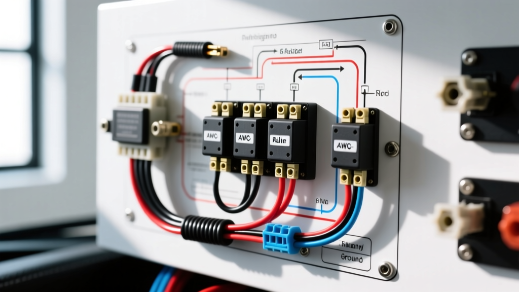
Why Race Cars Require Relay-Switched Panels
When building a dedicated track vehicle, the electrical system must be robust, serviceable, and fire-resistant. A common beginner mistake is routing high-current power wires directly through the firewall and into the cockpit to power dashboard switches. This not only creates a massive fire hazard in the event of a short circuit but also causes severe voltage drop, starving critical components like fuel pumps and cooling fans of the voltage they need to operate efficiently. The solution is a properly designed race car switch panel with relays. By using relays, you keep the heavy-gauge power wiring in the engine bay or chassis, while only running low-current 18 AWG trigger wires to the cockpit switches.
Standard automotive toggle switches, such as the popular Carling V-Series, are typically rated for a maximum of 20 amps. However, inductive loads like electric water pumps and radiator fans can draw massive current spikes upon startup. Running these loads directly through a switch will cause the internal contacts to arc, overheat, and eventually melt. Relays act as heavy-duty remote-controlled switches, allowing a low-amperage cockpit switch to safely control a high-amperage engine bay component.
Anatomy of the ISO 7588 5-Pin Automotive Relay
The backbone of any race car switch panel is the standard Bosch-style 5-pin relay, governed by the ISO 7588 standard. While 4-pin relays exist, the 5-pin variant is preferred in motorsport because it includes a Normally Closed (NC) terminal, which can be utilized for safety cut-offs or indicator light logic. For standard on/off accessories, you will primarily use four of the five pins.
| Pin Number | Function | Circuit Type | Typical Wire Gauge |
|---|---|---|---|
| 30 | Common (Battery Power In) | High Current Load | 12 to 10 AWG |
| 85 | Coil Ground | Low Current Trigger | 18 AWG |
| 86 | Coil Power (From Switch) | Low Current Trigger | 18 AWG |
| 87 | Normally Open (Power Out to Load) | High Current Load | 12 to 10 AWG |
| 87a | Normally Closed (Unused in basic setups) | High Current Load | N/A |
When the cockpit switch is flipped, it sends 12V to Pin 86. Pin 85 is grounded to the chassis. This energizes the internal electromagnetic coil, pulling the contactor down from Pin 87a to Pin 87, completing the high-current circuit from the battery (Pin 30) to your accessory (Pin 87).
Selecting the Right Wire: SAE J1128 Standards
Never use standard PVC-insulated wire (GPT) found in big-box hardware stores for a race car. Engine bays regularly exceed 220°F (104°C), which will melt PVC insulation and cause dead shorts. According to the SAE J1128 Standard for Low Tension Primary Cable, you must use cross-linked polyethylene (XLPE) insulated wire, specifically GXL or TXL. TXL (Thin-wall) is preferred in motorsport for its flexibility and weight savings while maintaining a 125°C continuous temperature rating.
| Component / Load | Max Amp Draw | TXL Wire Size (AWG) | SAE Recommended Color | MaxiFuse Size |
|---|---|---|---|---|
| EFI Fuel Pump | 15A | 14 AWG | Light Blue | 20A |
| Primary Cooling Fan | 25A | 10 AWG | Green | 30A |
| Electric Water Pump | 10A | 16 AWG | Brown | 15A |
| Switch Panel Trigger (Coil) | 2A | 18 AWG | White | 5A (Blade) |
Step-by-Step: Wiring the Switch Panel to the Relays
To build a reliable race car switch panel with relays, follow this systematic routing procedure to ensure clean power delivery and easy troubleshooting.
1. Establish the High-Current Power Feed
Run a heavy-gauge main power cable (e.g., 4 AWG or 2 AWG) from the positive battery terminal to a centralized Power Distribution Block (PDB) mounted in the engine bay or firewall. This main feed must be protected by a high-amperage ANL or Class-T fuse located within 18 inches of the battery positive post. From the PDB, run your individual 10-14 AWG load wires to Pin 30 of each relay.
2. Route the Low-Current Cockpit Trigger Circuit
Run a single 18 AWG fused power feed through the firewall to your cockpit switch panel. This single wire will daisy-chain through the center input terminals of all your toggle switches. From the output terminal of each switch, run an 18 AWG wire back through the firewall to Pin 86 on the corresponding relay in the engine bay.
3. Connect the Load and Ground
Connect Pin 87 of the relay to the positive terminal of your accessory (e.g., the fuel pump). Finally, ground Pin 85 of the relay. While you can ground Pin 85 to the chassis, best practice in motorsport is to run Pin 85 back to a centralized grounding busbar to prevent ground loops and ensure consistent coil energization.
Critical Terminations, Grounding, and EMI Suppression
The reliability of your race car switch panel with relays depends entirely on the quality of your terminations. Soldering is generally discouraged in high-vibration motorsport environments because solder wicks up into the wire strands under heat, creating a rigid point that will eventually fatigue and snap. Instead, use open-barrel crimp terminals (like those from Molex or TE Connectivity) applied with a ratcheting crimp tool. Always seal your connections with adhesive-lined dual-wall heat shrink to prevent moisture ingress and corrosion.
Suppressing Inductive Kickback (Flyback Diodes)
When a relay coil de-energizes, the collapsing magnetic field sends a high-voltage spike backward through the trigger circuit. In modern race cars with standalone ECUs or digital dashboards, this electromagnetic interference (EMI) can cause ECU resets or corrupt CAN-bus data. To prevent this, solder a 1N4001 flyback diode across Pins 85 and 86 on the relay. The diode's stripe (cathode) must face Pin 86 (the 12V switch side). This safely recirculates the voltage spike back into the coil, protecting your sensitive electronics.
Star Grounding Strategy
Avoid daisy-chaining grounds from one component to the next. Use a 'star ground' topology where every high-current load and relay coil ground wires to a single, dedicated chassis stud. Scrape away all paint and powder coating at the grounding point down to bare metal. Use a serrated flange nut or a star washer to bite into the metal, ensuring a zero-resistance connection as outlined in marine and race safety guidelines like SAE J1171 Ignition Protection.
Troubleshooting Common Race Car Electrical Faults
Even with meticulous planning, electrical gremlins occur on track days. Use this decision tree to diagnose issues with your relay-switched panel:
- Symptom: Relay clicks, but the accessory does not turn on.
- Cause: High resistance on the load side. Pin 30 or Pin 87 has power, but the circuit cannot carry the amperage.
- Fix: Check for a blown inline fuse, a loose crimp on the accessory positive terminal, or a poor chassis ground at the accessory itself. Perform a voltage drop test across the load circuit while the relay is engaged.
- Symptom: Cockpit toggle switch becomes hot to the touch or melts.
- Cause: The switch is carrying the full load current, meaning the relay coil is not being used, or the relay has failed internally and bypassed the trigger circuit.
- Fix: Verify that the switch is only carrying 18 AWG wire to Pin 86. If wired correctly, replace the relay, as the internal contacts may have welded together.
- Symptom: Relay chatters or buzzes rapidly without engaging the load.
- Cause: Insufficient voltage reaching Pin 86, or a poor ground on Pin 85. The coil is energizing just enough to pull the contactor, but the voltage drops immediately, releasing it in a rapid cycle.
- Fix: Check for undersized trigger wiring (long runs of 20 AWG or smaller will cause voltage drop). Upgrade the trigger wire to 18 AWG or 16 AWG and verify the ground path to the chassis or busbar.
By mastering these fundamentals, your race car switch panel with relays will provide years of reliable, safe, and easily serviceable power distribution, allowing you to focus on lap times rather than electrical gremlins in the paddock.