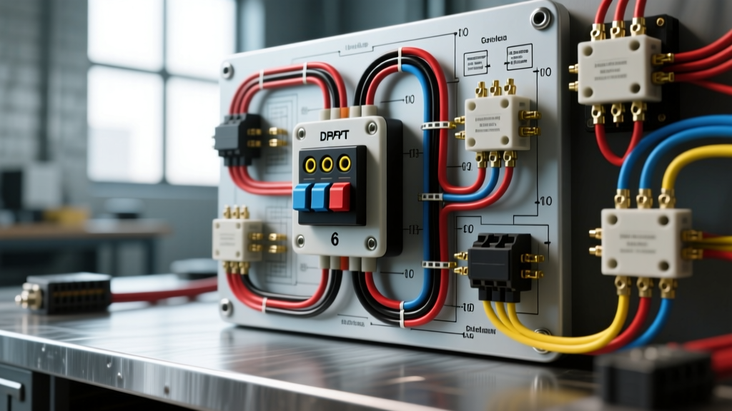
Introduction to Up Down Rocker Switches in Automotive Builds
When integrating linear actuators, snow plows, dump beds, or winches into a custom truck or off-road rig, controlling the direction of a DC motor is a fundamental requirement. An up down rocker switch provides a tactile, dashboard-friendly interface to reverse the polarity of a 12V or 24V DC circuit. However, beginners often make the critical mistake of routing high-amperage loads directly through the switch's internal copper contacts, leading to melted housings, voltage drops, and potential electrical fires.
This guide breaks down the beginner-friendly fundamentals of DPDT (Double Pole Double Throw) rocker switch pinouts, the internal crossover (H-bridge) mechanism, and the absolute necessity of relay isolation for high-draw automotive accessories. Whether you are wiring a 5-amp power tailgate actuator or a 300-amp recovery winch, understanding the underlying electrical architecture is critical for a safe, reliable installation.
Momentary vs. Maintained: Choosing the Right Action
Before cutting any wire, you must select the correct switch action for your specific application. Rocker switches generally come in two configurations for up/down control:
- Maintained (ON-OFF-ON): The switch stays in the UP or DOWN position when released. This is ideal for linear actuators on power tonneau covers, dump beds, or adjustable suspension components where continuous power is required to hold or move a load over a longer duration.
- Momentary (MOM-OFF-MOM): The switch springs back to the center OFF position when released. This is a strict safety requirement for recovery winches, snow plows, and crane hoists. If the operator becomes incapacitated or lets go of the switch, the circuit immediately breaks, preventing uncontrolled spooling or lifting.
Understanding the 6-Pin DPDT Configuration
To reverse a standard DC motor, you must swap the positive and negative feeds to the motor terminals. A Single Pole Double Throw (SPDT) 3-pin switch cannot do this alone. You need a 6-pin DPDT switch configured as an internal crossover, effectively acting as a manual H-bridge.
In a standard 6-pin rocker switch, the pins are divided into two columns (Left and Right) and three rows (Top, Middle, Bottom). The middle pins are the "Common" outputs, while the top and bottom pins are the "Inputs."
The Internal Crossover Pinout Chart
The table below details the standard wiring configuration for a 6-pin DPDT up down rocker switch used for low-draw (under 15A) reversing circuits. Note that the internal jumper bridges the top and bottom pins to create the polarity swap.
| Pin Position | Pin Number | Wire Function | Connection Logic (Internal) |
|---|---|---|---|
| Top Left | 1 | +12V Battery Source | Jumpered to Pin 4 |
| Middle Left | 2 | Motor Wire A (Output) | Common (Connects to 1 or 3) |
| Bottom Left | 3 | Ground (Chassis) | Jumpered to Pin 6 |
| Top Right | 4 | +12V Battery Source | Jumpered to Pin 1 |
| Middle Right | 5 | Motor Wire B (Output) | Common (Connects to 4 or 6) |
| Bottom Right | 6 | Ground (Chassis) | Jumpered to Pin 3 |
How it works: When you press the switch UP, Pin 1 connects to Pin 2 (sending +12V to Motor A), and Pin 6 connects to Pin 5 (sending Ground to Motor B). The motor spins forward. When you press DOWN, Pin 3 connects to Pin 2 (Ground to Motor A), and Pin 4 connects to Pin 5 (+12V to Motor B). The polarity reverses, and the motor spins backward.
The High-Draw Rule: Why You Must Use Relays
The internal copper contacts of a standard marine or automotive rocker switch are typically rated for 16A to 20A at 12V DC. If you are wiring an electric dump bed actuator that pulls 25A under load, or a winch that pulls 300A, running that current through the rocker switch will instantly overheat the terminals. According to Blue Sea Systems circuit protection guidelines, continuous loads should not exceed 80% of a switch's rated capacity.
For any motor drawing over 15 amps, the up down rocker switch must only be used to trigger the coils of heavy-duty automotive relays or a dedicated winch solenoid contactor. The switch handles the low-amperage "control circuit," while the relays handle the high-amperage "load circuit."
Step-by-Step: Wiring a DPDT Switch to a Dual Relay Harness
For moderate-draw reversing circuits (e.g., 20A-40A linear actuators or power windows), you can build a reversing harness using two standard 5-pin SPDT Bosch-style relays. This eliminates the need for the internal switch jumpers and relies on the relays to swap polarity.
Step 1: Select the Right Wire Gauge and Fuses
Wire sizing is dictated by the maximum amperage draw and the length of the wire run. According to SAE J1128 standards for low-tension primary cable, you must account for voltage drop and heat dissipation in the engine bay.
- Control Circuit (Switch to Relay Coils): 14 AWG primary wire. Fuse at 5A.
- Load Circuit (Battery to Relays to Motor): 10 AWG for up to 30A; 6 AWG for up to 50A. Fuse at 125% of the motor's maximum stall current.
Step 2: Wiring the Control Circuit (Low Amp)
Instead of using the 6-pin crossover method, you will use the DPDT switch to route +12V to the relay coils. Wire your switch as follows:
- Pin 1 & 4 (Jumpered): Connect to a switched +12V ignition source (fused at 5A).
- Pin 2 (Middle Left): Run to Relay 1, Pin 86 (Coil +).
- Pin 5 (Middle Right): Run to Relay 2, Pin 86 (Coil +).
- Pin 3 & 6: Leave empty (or use them for switch LED ground if your rocker features illumination).
- Relay 1 & 2 Pin 85 (Coil -): Ground securely to the chassis using a ring terminal and a star washer to bite through the paint.
Step 3: Wiring the Load Circuit (High Amp)
Now, configure the two relays to act as the H-bridge for the high-current motor feed:
- Relay 1 & 2 Pin 30 (Common): Connect to the main +12V battery post via a heavy-duty ANL or Mega fuse.
- Relay 1 Pin 87 (Normally Open): Connect to Motor Wire A.
- Relay 2 Pin 87 (Normally Open): Connect to Motor Wire B.
- Relay 1 Pin 87a (Normally Closed): Jumper to Relay 2 Pin 87 (Motor Wire B).
- Relay 2 Pin 87a (Normally Closed): Jumper to Relay 1 Pin 87 (Motor Wire A).
Note: When Relay 1 triggers, +12V flows to Motor A, and Motor B grounds through Relay 2's 87a pin (if configured with a ground bus) or utilizes a specialized DPDT relay setup. For high-amperage winches, bypass this entirely and use a pre-wired 4-solenoid winch contactor pack designed to accept simple +12V triggers from the rocker switch.
Standard SAE Wire Color Codes for DC Reversing Circuits
Maintaining a standardized color code is vital for future troubleshooting. While custom looms vary, adhering to standard automotive and marine DC color codes ensures that any technician can understand your harness. Reference standard Littelfuse automotive relay guides for terminal identification.
- Red: Main +12V Battery Feed (Unswitched, High Amp)
- Black: Main Chassis Ground (High Amp)
- Yellow: Forward / UP Trigger (Switched +12V to Relay Coil)
- Blue: Reverse / DOWN Trigger (Switched +12V to Relay Coil)
- Orange: Switched Accessory +12V (Ignition fed source for switch input)
- White: Switch LED Illumination Ground
Termination and Environmental Protection
The engine bay and undercarriage are hostile environments. Moisture intrusion into a rocker switch terminal will cause galvanic corrosion, increasing resistance and generating heat. Always use 3:1 adhesive-lined marine heat shrink over your crimp connections. The internal thermoplastic adhesive melts and seals the wire strands, preventing capillary action from drawing water up into the copper. For battery lugs and relay bus bars, torque 3/8" hardware to 10-12 ft-lbs to ensure maximum surface area contact and prevent arcing.
Troubleshooting Common Up Down Switch Failures
If your custom installation is malfunctioning, use this diagnostic tree to isolate the fault:
- Symptom: Motor only moves in one direction.
Cause: Blown internal jumper inside the DPDT switch, or a failed coil on one of the reversing relays. Use a multimeter to check for +12V at both middle pins (2 and 5) when toggling the switch. - Symptom: Switch housing is hot to the touch or smells like melting plastic.
Cause: Overloading. You are pulling more than 16A through the switch contacts. Immediately disconnect the battery and rewire the system using heavy-duty relays or a solenoid contactor. - Symptom: Motor stutters or moves sluggishly in one direction only.
Cause: High resistance on one side of the H-bridge. Check the ground connection for the specific relay controlling that direction. Paint, rust, or a loose star washer will cause severe voltage drop under load. - Symptom: Switch LEDs illuminate, but motor does not engage.
Cause: The switch illumination circuit is independent of the load circuit. You likely have a blown main ANL fuse on the +12V load feed, or the relay coil ground (Pin 85) has lost continuity.
Conclusion
Mastering the up down rocker switch is a rite of passage for custom automotive wiring. By understanding the difference between maintained and momentary actions, correctly mapping the 6-pin DPDT crossover for low-draw circuits, and strictly enforcing relay isolation for high-draw motors, you ensure your accessories operate reliably in the harshest conditions. Always prioritize adhesive-lined heat shrink, proper AWG sizing, and strict adherence to SAE circuit protection standards to build a harness that lasts the lifetime of the vehicle.