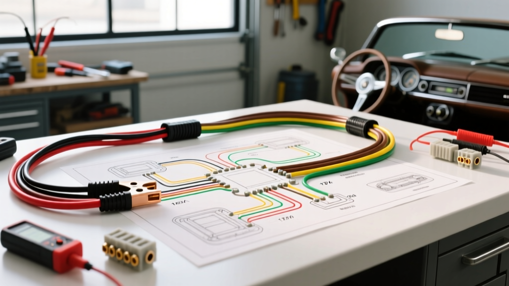
Introduction to the Woods Auto Electrics Methodology
When approaching a complex classic car restoration or a bespoke custom build, deciphering the electrical schematic is the most critical step in ensuring reliability and safety. The Woods Auto Electrics methodology represents a gold-standard approach to reading, tracing, and upgrading classic 12V negative-earth wiring looms. Unlike modern multiplexed CAN-bus systems, classic looms rely on point-to-point analog circuits, making a complete wiring diagram walkthrough essential for diagnosing voltage drops, identifying parasitic draws, and executing modern relay upgrades. In this comprehensive guide, we will walk through a traditional bespoke 12V schematic, breaking down the starter solenoid circuit, the alternator excitation loop, and the ignition ballast bypass, while providing exact AWG specifications and color codes.
Decoding the Schematic: Wire Color Codes and AWG Standards
Before tracing any circuit, an auto electrician must understand the color-coding legend. The Woods Auto Electrics standard heavily borrows from classic British Standard (BS AU7) and Lucas electrical color codes, which categorize wires by their power source and switching state. Referencing the SAE J1128 Standard for low-tension primary cables, we must also pair these color codes with the correct American Wire Gauge (AWG) to prevent thermal overloading and excessive voltage drop.
| Wire Color | Circuit Function | Standard AWG | Metric (mm²) | Fusing Requirement |
|---|---|---|---|---|
| Brown | Unfused Battery Feed (Constant 12V) | 10 AWG to 4 AWG | 5.0mm² to 20mm² | Main Fusible Link |
| White | Ignition Switched (Hot in Run/Start) | 14 AWG | 2.0mm² | Fused at Block |
| Red/White | Fused Ignition Feed (Accessories) | 16 AWG | 1.5mm² | 5A - 15A Inline |
| Blue | Sidelights / Parking Lamps | 18 AWG | 0.8mm² | 10A Fuse |
| Blue/White | Headlight High/Low Beam Feeds | 14 AWG | 2.0mm² | 20A Fuse |
| Black | Earth / Ground Return | Varies | Varies | None |
Using undersized wire is a leading cause of electrical fires in classic restorations. Always verify the continuous amperage draw of your components and consult standard ampacity charts to ensure your wire gauge can handle the load with a 20% safety margin.
Circuit Walkthrough 1: Battery, Starter Solenoid, and Ignition Switch
The foundation of any automotive electrical system is the high-amperage cranking circuit. In a standard Woods Auto Electrics diagram, the main battery feed originates at the positive terminal using a heavy-duty 2 AWG (35mm²) black or red cable (depending on regional ground conventions; we assume negative earth here, so the positive feed is often Red or Brown). This cable routes directly to the 'B' (Battery) terminal on the starter solenoid.
Tracing the Cranking Signal
When the ignition switch is turned to the 'Start' position, a 16 AWG (1.5mm²) White/Red wire carries 12V from the ignition switch to the 'S' (Start) terminal on the solenoid. This low-amperage signal (typically under 15 amps) energizes the solenoid's internal pull-in and hold-in coils. The heavy copper contactor inside the solenoid then bridges the 'B' and 'M' (Motor) terminals, sending upwards of 250 amps through a 2 AWG cable down to the starter motor's main post.
Diagnostic Insight: If you experience a single loud 'click' but no engine cranking, use a multimeter to measure voltage at the 'M' terminal while an assistant holds the key in the 'Start' position. If battery voltage is present at 'B' but drops below 9V at 'M' during cranking, the internal solenoid contacts are pitted and the solenoid must be replaced.
Circuit Walkthrough 2: The Lucas 18ACR Alternator 3-Pin Connector
Transitioning from the starter to the charging system, classic diagrams frequently utilize the ubiquitous Lucas 18ACR or A115-type alternator. The wiring harness interfaces with the alternator via a specific 3-pin plastic connector. Understanding this pinout is crucial, as miswiring will instantly destroy the internal diode pack or prevent the alternator from exciting.
| Pin Number | Terminal Marking | Wire Color | Function & Routing |
|---|---|---|---|
| Pin 1 | IND (Warning) | Brown/Yellow | Routes to the dash charge warning bulb (2.2W). Provides the initial excitation current to the rotor field. |
| Pin 2 | F (Field/Tacho) | White/Green | Pulsed DC signal routing to an electronic tachometer or diagnostic port. |
| Pin 3 | B+ (Output) | Brown (Heavy) | Main charging output. Routes directly to the battery positive or starter solenoid 'B' terminal via 8 AWG wire. |
According to Haynes Automotive Wiring Basics, the warning bulb on Pin 1 is not just an indicator; it is a critical electrical component. The 2.2-watt bulb limits current but allows approximately 180 milliamps to flow into the alternator's rotor, establishing the magnetic field required to begin generating alternating current. If an owner upgrades to an LED dash bulb without installing a parallel 50-ohm, 5-watt dummy resistor, the alternator will fail to excite, resulting in a dead battery.
Bypassing the Ballast Resistor During Cranking
Many classic ignition systems utilize a ballast resistor wire (often a resistive Pink or White/Blue wire) to drop the voltage to the ignition coil from 14V (running) to 9V, preventing the points from burning out. However, during cranking, system voltage can drop as low as 9V. If this reduced voltage passes through the ballast, the coil will only receive 6V, resulting in a weak, orange spark and a no-start condition.
The wiring diagram solves this via the Ignition Bypass Circuit. A dedicated 16 AWG White/Blue wire runs from the 'I' (Ignition) terminal on the starter solenoid directly to the positive terminal of the ignition coil. When the solenoid engages, this wire feeds full, unresisted battery voltage (minus cranking voltage drop) directly to the coil, ensuring a hot, blue spark exactly when the engine needs it most. Once the key is released to the 'Run' position, the 'I' terminal de-energizes, and the coil resumes operation via the ballast feed.
Modernizing the Loom: Headlight Relay Upgrades
A complete Woods Auto Electrics walkthrough is incomplete without addressing the inherent flaws of classic headlight switches, which route the full amperage of the halogen headlights (up to 15A per pair) through the delicate copper contacts of the dashboard switch and bulkhead connectors. This results in severe voltage drop and melted switch plastics.
The Dual-Relay Upgrade Schematic
To rectify this, the diagram is modified to include two standard Bosch-style 5-pin relays (one for low beam, one for high beam).
- Pin 86 (Coil +): Connect to the original Blue/White headlight feed from the factory switch. This now acts only as a low-amperage trigger signal.
- Pin 85 (Coil -): Connect to a clean, unpainted chassis ground using 16 AWG Black wire and a ring terminal.
- Pin 30 (Common Input): Connect directly to the battery positive via a new 10 AWG Brown wire, protected by a 20A inline ATO fuse.
- Pin 87 (Normally Open Output): Connect to the headlight harness feed, delivering full, unimpeded 14.2V directly to the bulbs.
- Pin 87a (Normally Closed): Left unused and insulated.
This upgrade reduces the voltage drop at the headlight bulb from an average of 2.5V down to less than 0.2V, increasing lumen output by up to 40% while completely preserving the factory dashboard switch.
Real-World Failure Modes and Bulkhead Diagnostics
When troubleshooting using the diagram, auto electricians must look beyond the copper wire itself and focus on the transition points. The most common failure mode in classic looms is the bulkhead connector—the multi-pin plug that passes the wiring harness through the firewall from the engine bay to the cabin.
Over decades of thermal cycling and moisture intrusion, the brass male and female pins inside the bulkhead connector oxidize, creating high resistance. According to standard diagnostic procedures, a healthy connection should exhibit a voltage drop of no more than 10 millivolts (0.010V) per connection under load. To test this:
- Set your digital multimeter to the DC Millivolt (mV) scale.
- Turn on the high-load circuit (e.g., heater blower motor or headlights).
- Place the red probe on the engine-side pin and the black probe on the cabin-side pin of the exact same wire circuit.
- If the meter reads above 200mV (0.2V), the terminal is suffering from micro-corrosion.
The definitive repair is to extract the pins using a proper terminal release tool, clean them with fiberglass scratch pens, and apply a dielectric grease like Sanchem No-Ox-Id A-Special before re-seating. In severe cases where the plastic housing is brittle, the entire bulkhead connector must be bypassed or replaced with a modern sealed Deutsch DT or Weather-Pack connector system to ensure long-term environmental sealing.
By meticulously following this Woods Auto Electrics diagram walkthrough, verifying wire gauges against SAE standards, and upgrading high-load circuits with modern relays, you can transform an unreliable classic wiring loom into a robust, modernized electrical architecture capable of supporting today's high-draw accessories and lighting systems.