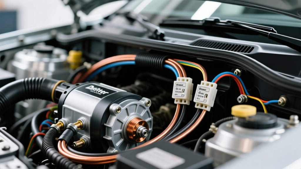
Introduction to Richter Auto Electric High-Output Upgrades
Upgrading your vehicle's charging system is essential when adding high-draw accessories like off-road LED light bars, heavy-duty winches, or competition-level car audio amplifiers. The Richter Auto Electric high-output alternator series (typically ranging from 220A to 300A) provides the necessary amperage to keep auxiliary systems running without draining the battery. However, simply bolting on a high-amp unit is not enough; the factory wiring harness is usually rated for only 80A to 120A and will melt or cause severe voltage drop under a 250A load. This practical installation guide details the exact procedures, wire gauges, and connector pinouts required to safely integrate a Richter Auto Electric alternator and heavy-duty wiring harness into your vehicle's electrical architecture.
Pre-Installation: Load Calculation and Component Prep
Before cutting any wire, verify your total electrical load. Sum the peak amperage of all accessories. A general rule of thumb established by the SAE J555 Alternator Standard is to select an alternator rated for at least 20% more than your calculated continuous load to ensure longevity and prevent diode rectifier heat soak. Once verified, disconnect the negative battery terminal and isolate it to prevent accidental short circuits during the B+ terminal routing phase.
Required Tools and Materials
| Item | Specification / Requirement |
|---|---|
| Main Power Wire | 1/0 AWG Oxygen-Free Copper (OFC) Welding Wire |
| Sense / Exciter Wire | 10 AWG TXL Cross-Linked Polyethylene Wire |
| Terminal Crimper | Hydraulic Crimper with 1/0 AWG and 10 AWG Hex Dies |
| Heat Shrink | Dual-Wall Adhesive-Lined Polyolefin (3:1 Shrink Ratio) |
| Overcurrent Protection | 250A ANL Fuse and Marine-Grade Fuse Holder |
| Connector Kit | Delphi Packard Metri-Pack 280 Series (2-Pin or 4-Pin) |
Step-by-Step Installation Procedure
Step 1: Battery and Chassis Ground Preparation
High-amperage alternators require an impeccable return path to the battery. Factory ground straps are often undersized and prone to corrosion. Begin by upgrading the 'Big 3' wiring. Run a dedicated 1/0 AWG ground cable from the alternator casing (using the dedicated M8 ground boss on the Richter unit) directly to the engine block. Next, run a second 1/0 AWG cable from the engine block to the chassis, and a third from the chassis to the negative battery post. Use a wire brush to remove all paint, powder coat, and rust from the mounting surfaces to ensure bare metal-to-metal contact. Apply a thin layer of dielectric grease over the crimped ring terminals after torquing to prevent galvanic corrosion.
Step 2: Routing the Richter 1/0 AWG Main Power Cable
The main B+ output cable must be routed away from exhaust manifolds, steering shafts, and sharp chassis edges. Measure the distance from the alternator B+ post to the positive battery terminal, adding 12 inches for service loops and error. Cut the 1/0 AWG red OFC wire. Strip 5/8 inch of insulation from both ends. Using the hydraulic crimper with the 1/0 AWG hex die, crimp a 3/8 inch copper ring terminal onto the alternator end, and a 5/16 inch ring terminal for the ANL fuse holder on the battery end. Seal both crimps with adhesive-lined heat shrink. Critical Safety Step: The 250A ANL fuse must be installed within 18 inches of the positive battery terminal to protect the entire length of the cable in the event of a dead short.
Step 3: Exciter Wire and Sense Wire Integration
The Richter Auto Electric internal voltage regulator relies on two critical low-amperage signals: the Ignition Exciter (L-Terminal) and the Battery Sense (S-Terminal). Do not reuse the factory exciter wire if it is smaller than 14 AWG, as voltage drop across the factory harness will cause the regulator to overcompensate, leading to system voltages exceeding 15.2V and boiling the battery electrolyte. Run a dedicated 10 AWG yellow wire from the alternator S-terminal directly to the positive battery post (fused at 10A). Run a 10 AWG white wire from the L-terminal to an ignition-switched 12V source in the fuse box. This ensures the alternator only engages when the engine is running, preventing parasitic drain.
Step 4: Delphi Pigtail Pinout and Connector Assembly
Most Richter high-amp units utilize a standardized Delphi Packard Metri-Pack 280 connector for the regulator harness. Proper pin insertion and weather-seal alignment are crucial to prevent moisture ingress, which is the leading cause of regulator failure. Refer to the pinout table below when assembling the pigtail.
| Pin Position | Wire Color | AWG | Function / Destination |
|---|---|---|---|
| Pin A (Top Left) | White | 10 AWG | Ignition Exciter (Switched 12V) |
| Pin B (Top Right) | Yellow | 10 AWG | Battery Sense (Direct to B+ Post) |
| Pin C (Bottom Left) | Black | 12 AWG | Regulator Ground (To Alternator Case) |
| Pin D (Bottom Right) | Green | 14 AWG | Tachometer / ECU Field Signal |
Use the Delphi-specific terminal crimp tool to ensure the wire crimp and insulation crimp tabs are folded correctly. Slide the silicone weather seals over the wire before crimping. Push the terminals into the plastic housing until you hear a distinct click, then gently tug back to verify the secondary locking tang has engaged.
Step 5: Alternator Mounting and Torque Specifications
When mounting the Richter alternator, ensure the pivot ear and bracket mating surfaces are clean. Install the mounting bolts hand-tight to allow for alignment. Before applying final torque, route the serpentine belt and use a straight-edge or laser alignment tool to verify the alternator pulley is perfectly in plane with the crankshaft and idler pulleys. Misalignment by as little as 2mm will cause premature belt wear and bearing failure. Torque the M10 mounting bolts to 35 Nm (26 lb-ft). Torque the B+ terminal nut to 12 Nm (9 lb-ft)—do not overtighten, as this will strip the copper threads on the internal rectifier block.
Post-Installation Testing and Voltage Drop Analysis
According to AutoShop 101 Charging System Diagnostics, a visual inspection is insufficient to verify a high-amp install. You must perform a voltage drop test under load. Start the engine and turn on all high-draw accessories (headlights, HVAC blower on max, heated seats). Using a digital multimeter, place the red probe on the alternator B+ post and the black probe on the positive battery terminal. The reading must be less than 0.10V. Next, test the ground side: place the red probe on the alternator casing and the black probe on the negative battery terminal. This reading must be less than 0.05V. If your readings exceed these thresholds, re-crimp your terminals or clean your ground mating surfaces.
Real-World Troubleshooting and Failure Modes
Even with a meticulous installation, aftermarket high-output alternators can exhibit specific quirks. Below is a decision tree for common Richter Auto Electric installation issues:
- Symptom: Alternator whines or whistles at idle, voltage fluctuates between 13.2V and 14.8V.
Cause: The Sense Wire (Pin B) is routed too close to high-tension ignition wires or fuel injector harnesses, introducing Electromagnetic Interference (EMI) to the regulator.
Fix: Reroute the sense wire away from EMI sources, or wrap the 10 AWG sense wire in copper-braided shielding and ground the shield at the battery negative. - Symptom: Battery overcharges (15.5V+) and smells like sulfur.
Cause: High resistance on the ground circuit forcing the regulator to read a false low voltage.
Fix: Verify the 12 AWG Pin C ground wire has continuity to the alternator case, and ensure the alternator case is properly grounded to the engine block via the 1/0 AWG strap. - Symptom: Alternator does not engage until engine RPM exceeds 2,500.
Cause: Weak exciter signal or slipping serpentine belt.
Fix: Check the 10 AWG Pin A exciter wire for a solid 12V ignition signal. If voltage is present, check belt tensioner deflection (should not exceed 1/2 inch under thumb pressure).
For further technical reference on wire gauge ampacity and thermal limits in engine bays, consult the MAD Electrical Wire Gauge Technical Guide. Proper execution of this Richter Auto Electric installation protocol will ensure a reliable, high-amperage charging system capable of supporting the most demanding automotive electrical architectures.