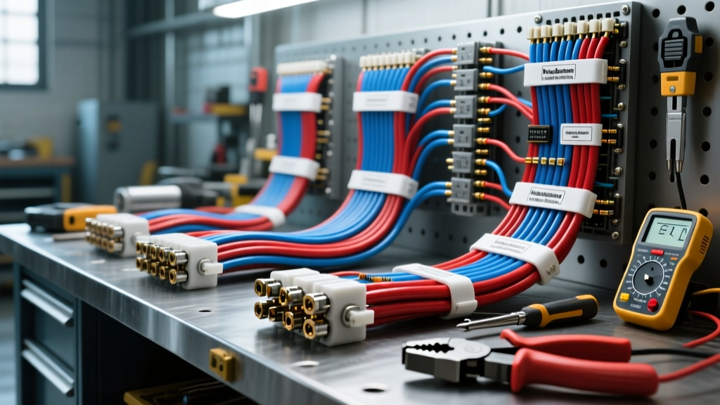
The Hutcherson Auto Electric Standard in Custom Wiring
When classic car restorers and hot rod builders demand flawless electrical reliability, they look to the methodologies pioneered by top-tier shops like Hutcherson Auto Electric. A custom wiring harness installation is not merely about connecting point A to point B; it is an exercise in thermal management, voltage drop mitigation, and long-term vibration resistance. Upgrading a classic muscle car or custom street rod from its original 50-year-old PVC wiring to a modern, high-capacity system requires strict adherence to professional automotive electrical standards.
This practical how-to guide breaks down the professional installation process, translating the high-end shop techniques of Hutcherson Auto Electric into actionable steps for advanced DIYers and junior technicians. We will cover wire selection, circuit mapping, firewall integration, relay architecture, and professional termination.
Phase 1: Wire Selection and Circuit Planning
The most critical mistake in amateur wiring is using standard hardware-store PVC wire. Under-hood temperatures in a V8 engine bay frequently exceed 200°F (93°C), which causes standard PVC insulation to become brittle, melt against exhaust headers, and eventually short out.
Specify TXL or GXL Wire
Professional auto electricians exclusively use Cross-Linked Polyethylene (TXL or GXL) wire. According to SAE Standard J1128, TXL wire features a thin-wall insulation that withstands continuous temperatures up to 125°C (257°F) and offers superior resistance to abrasion and chemicals. The thin wall also allows for smaller bundle diameters, making it easier to pull through tight chassis grommets.
Standardizing Color Codes
To ensure future serviceability, adopt a strict color-code standard across the entire vehicle. A common professional standard (heavily utilized in GM and classic Ford restorations) includes:
- Red: Constant 12V+ Battery Feed (Fused)
- Pink: Switched 12V+ Ignition Feed
- Black: Primary Ground
- Yellow: Left Turn / Brake
- Dark Green: Right Turn / Brake
- Brown: Running / Parking Lights
- White: Headlight High Beam Feed
- Light Green: Headlight Low Beam Feed
Phase 2: Routing and Firewall Integration
The firewall pass-through is the most common failure point for electrical shorts. The Hutcherson Auto Electric approach dictates that no wire should ever pass through bare sheet metal.
- Locate the Factory Grommet: Utilize the existing upper firewall grommet, typically located behind the driver-side valve cover on classic V8s. If building a custom tube chassis, weld a dedicated 2-inch steel pass-through ring into the firewall.
- Size the Grommet Correctly: The rubber grommet must be sized to the exact outer diameter (OD) of the wire bundle. A loose grommet will allow engine bay heat and carbon monoxide to enter the cabin.
- Lubricate and Pull: Wrap the wire bundle tip tightly with electrical tape to form a smooth bullet nose. Apply a generous amount of silicone dielectric grease to the tape and the inside of the grommet. Pull from the cabin side using a fish tape, never yanking the wires themselves, which can stretch the copper strands and alter their AWG resistance.
For detailed routing diagrams and firewall best practices, reference the technical bulletins provided by American Autowire Tech Tips, which align closely with professional shop standards for classic GM and Ford applications.
Phase 3: Relay Integration for High-Draw Circuits
Classic vehicles were designed for low-draw sealed beam headlights and small wiper motors. Modern upgrades like Halogen/HID headlights, dual 11-inch electric cooling fans, and high-pressure EFI fuel pumps will overload factory switches and melt 14 AWG wire runs over long distances due to voltage drop.
The Relay Architecture
Professional installations use Bosch-style 40A SPST (Single Pole Single Throw) or SPDT relays to move the high-current load away from the dash switches. The dash switch only carries the low-current trigger signal.
- Pin 30 (Power In): Fed directly from the fuse block or battery via 10 AWG Red wire.
- Pin 87 (Power Out): Feeds the high-draw component via 10 AWG or 12 AWG wire.
- Pin 85 (Trigger In): Connected to the dash switch output using 18 AWG wire.
- Pin 86 (Ground): Grounded locally to the chassis or tied to the ECU ground trigger for electric fans.
By using this architecture, the headlight switch on the dash only handles 0.5 amps to trigger the relay coil, while the heavy 15-amp headlight load travels a short, direct path from the battery to the relay, and then to the headlights, eliminating the notorious "dim headlight" issue in older cars.
Phase 4: Professional Termination and Crimping
Soldering is strictly avoided in high-vibration automotive environments. Solder wicks up into the wire strands via capillary action, creating a rigid, brittle point just above the solder joint that will eventually snap under engine vibration. The industry standard is a gas-tight mechanical crimp.
Using Delphi Weather-Pack Connectors
For any connection exposed to the elements (engine bay, taillights, undercarriage), use Delphi (Aptiv) Weather-Pack or Metri-Pack connectors. These feature silicone rubber seals that compress around the wire insulation, preventing moisture wicking.
- Strip the Wire: Use precision wire strippers to remove exactly 5/32" of insulation. Do not nick the copper strands.
- Select the Crimp Tool: Use a ratcheting crimper specific to the terminal type (e.g., Delphi M-200 or equivalent). Ratcheting tools ensure the crimp cycle is fully completed before releasing.
- The Crimp Anatomy: The terminal features two sets of wings. The wire wings must crush the bare copper strands into a cold-weld. The insulation wings must tightly grip the wire jacket to provide strain relief.
- Seal and Insert: Slide the silicone seal over the wire before crimping. After crimping, push the terminal into the nylon housing until the tang clicks. Pull back firmly (approx. 10 lbs of force) to verify the lock is engaged.
Phase 5: The Grounding Architecture
Over 80% of all automotive electrical gremlins—ranging from flickering gauges to erratic EFI idle surges—are caused by poor grounding. The Hutcherson Auto Electric method abandons "daisy-chain" grounding in favor of a dedicated Star Ground or Ground Bus system.
Executing a Perfect Chassis Ground
- Surface Prep: Use a 3M Roloc disc to strip the chassis down to bare, shiny steel at the grounding point. Never ground to paint, powder coat, or rust.
- Hardware Selection: Use a Grade 8 bolt or a dedicated welded ground stud. Place a star washer between the ring terminal and the bare metal to bite into the steel and prevent loosening from thermal expansion.
- Corrosion Protection: Once torqued to spec (typically 15-20 ft-lbs for a 5/16" or 3/8" bolt), coat the entire terminal and exposed bare metal in a thick layer of silicone dielectric grease or conductive anti-seize to prevent galvanic corrosion and moisture ingress.
Classic Vehicle Circuit Sizing Reference Chart
Use the following reference chart to size your wires and fuses correctly when building a custom harness for a classic V8 muscle car or street rod. Fuses are sized to protect the wire, not the component.
| Circuit Component | Recommended Wire Gauge (AWG) | Max Fuse Rating (ATO/ATC) | Notes / Professional Tips |
|---|---|---|---|
| Main Battery to Starter | 1/0 AWG or 2/0 AWG | 250A Mega Fuse | Use fine-strand welding cable for flexibility. |
| Alternator Output Feed | 8 AWG (100A+ Alt) | 100A ANL Fuse | Upgrade to 8 AWG if running a 1-Wire 100A+ alternator. |
| Headlights (Halogen/HID) | 10 AWG | 20A | Must use relay architecture; do not run through dash switch. |
| Dual Electric Cooling Fans | 10 AWG | 30A per fan | Use dedicated 40A relays and 30A circuit breakers for spike protection. |
| EFI Fuel Pump (In-Tank) | 12 AWG | 15A or 20A | Use a fuel pump safety relay tied to oil pressure switch. |
| Ignition Box (MSD/HEI) | 12 AWG | 15A | Requires clean, switched 12V. Do not share with ballast resistor. |
| Blower Motor (HVAC) | 12 AWG | 20A | High startup surge; use a slow-blow fuse if available. |
| Dash Gauges / Cluster | 16 AWG | 5A | Use a dedicated voltage limiter for vintage analog gauges. |
| ECU / TCM Main Power | 14 AWG | 10A | Must be grounded directly to the engine block, not the chassis. |
Final Testing and Voltage Drop Verification
Before reassembling interior panels or sealing the engine bay, perform a comprehensive voltage drop test. With the engine running and all high-draw accessories (fans, headlights, wipers) turned on, use a digital multimeter to measure the voltage between the alternator B+ terminal and the positive input of the component. A reading greater than 0.5V indicates excessive resistance in the wiring or a poor crimp, requiring immediate troubleshooting. By adhering to these rigorous standards, you ensure your custom vehicle operates with the reliability and safety expected from top-tier facilities like Hutcherson Auto Electric.