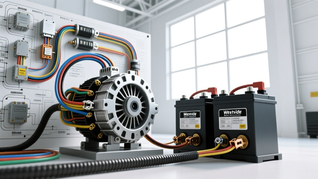
Introduction to Westside Auto Electrical Methodologies
When engineering high-current automotive charging systems for overlanding, heavy-duty towing, or mobile command centers, standard factory wiring harnesses quickly become the primary bottleneck. The Westside Auto Electrical methodology has emerged as a benchmark in the custom auto-electric industry, prioritizing marine-grade terminations, precise voltage regulation, and heavy-duty AWG sizing to eliminate voltage drop and thermal runaway. This advanced technical deep dive explores the core principles of the Westside Auto Electrical approach, specifically focusing on high-amperage alternator integration (200A+ systems), precision sense-wire routing, and DC-DC dual-battery isolation architectures.
The 'Big Three' Wiring Upgrade for High-Amp Systems
Upgrading to a 200A or 250A alternator (such as those from Mechman or Power Bastards) without upgrading the main chassis wiring is a critical failure point. Factory 4 AWG or 6 AWG battery cables will overheat, causing severe voltage drop and potentially melting insulation. The Westside Auto Electrical standard mandates a comprehensive 'Big Three' upgrade using cross-linked polyethylene (XLPE) insulated wire.
Wire Selection and Routing
For systems up to 250A, 1/0 AWG TXL (Thin Wall Cross-Linked) or SGT (Standard Battery Cable) is required. TXL is preferred in tight engine bays due to its smaller outer diameter and superior resistance to under-hood temperatures (rated up to 125°C continuous). According to SAE J1128 standards, TXL wire provides the necessary current-carrying capacity while minimizing harness bulk.
- Alternator B+ to Battery B+: 1/0 AWG Red TXL. Must be routed away from exhaust manifolds and sharp chassis edges. Use split-loom corrugated tubing with high-temp tape wrapping.
- Engine Block to Chassis Ground: 1/0 AWG Black TXL. Connects from the alternator mounting bracket or main engine lift eye to a clean, bare-metal point on the frame rail.
- Battery B- to Chassis Ground: 1/0 AWG Black TXL. Ensures the main battery negative has a zero-resistance path to the vehicle frame, completing the high-current return loop.
Grounding Best Practices and Torque Specifications
A common failure mode in custom auto electrical builds is poor ground termination. Paint, powder coating, and rust act as dielectric insulators. The Westside methodology requires sanding the chassis contact point down to bare, shiny metal. Use a stainless steel star washer between the copper lug and the chassis to bite through any microscopic oxidation. Apply a thin layer of dielectric grease over the completed joint to prevent galvanic corrosion. Torque M10 (3/8") ground bolts to 25-30 ft-lbs to ensure maximum surface area contact and prevent vibration-induced loosening.
Alternator Sense Wire Relocation
Modern alternators utilize an internal or external voltage regulator that relies on a 'sense' wire to determine system voltage. In factory configurations, this sense wire is often tapped into the under-hood fuse box or ignition switch circuit. When you introduce a 250A alternator and heavy auxiliary loads, the voltage drop across the factory harness can trick the regulator into overcharging the main battery to compensate for the perceived drop.
To achieve precision voltage regulation, the sense wire must be relocated directly to the main battery B+ post. Using 18 AWG Green/Yellow primary wire, run a dedicated sense line from the alternator's 'S' or 'Sense' pin directly to the positive battery terminal. This ensures the regulator reads the exact voltage at the battery, maintaining a strict 14.2V - 14.4V charging profile without overcompensating for harness resistance.
High-Output Pulley Ratios and Belt Slip Mitigation
A 250A alternator will not produce its rated output at idle if the pulley ratio is incorrect. The Westside Auto Electrical standard calculates the pulley ratio by dividing the crankshaft pulley diameter by the alternator pulley diameter. A minimum ratio of 2.8:1 is required for high-amp units to achieve peak output at 600-800 RPM idle.
However, increasing the ratio by installing a smaller alternator pulley drastically increases the load on the serpentine belt, leading to belt slip, squealing, and premature bearing failure. To mitigate this, upgrade to a heavy-duty automatic belt tensioner and a high-grip Kevlar-reinforced serpentine belt. In extreme cases, a dual-groove pulley setup with matched matched-length belts is required to distribute the rotational torque.
Dual-Battery Isolation: DC-DC Charger Architecture
For auxiliary battery systems, the Westside methodology strictly avoids basic Voltage Sensitive Relays (VSRs) or isolator diodes when charging AGM, Gel, or LiFePO4 (Lithium) batteries. VSRs simply parallel the batteries, forcing the alternator to treat a massive combined battery bank as a single load, which can trigger the alternator's internal thermal protection or cause lithium BMS shutdowns due to unregulated voltage spikes.
Instead, a high-quality DC-DC Battery Charger is utilized to isolate the starter battery from the auxiliary bank while providing a multi-stage charging profile. Below is the standard pinout and wiring specification for a 40A DC-DC charger integration.
| Terminal / Pin | Wire Color (Standard) | AWG Size | Function & Routing Notes |
|---|---|---|---|
| B+ IN | Red | 4 AWG | Main Starter Battery Input. Fused at 60A (Mega Fuse) within 18 inches of the battery. |
| B- IN | Black | 4 AWG | Common Ground Reference. Must share the same ground bus as the auxiliary battery negative. |
| IGN / D+ | Blue/White | 16 AWG | Ignition Sense. Tapped to a fuse that is only live when the key is in the 'ON/RUN' position. |
| B+ OUT | Red | 4 AWG | Auxiliary Battery Charge Output. Fused at 50A near the auxiliary battery positive post. |
| TEMP | Yellow/Green | 18 AWG | Battery Temperature Sensor. Ring terminal attached directly to the auxiliary battery negative post. |
Marine-Grade Terminations and Environmental Protection
The most critical aspect of the Westside Auto Electrical standard is the termination process. Under-hood environments are subjected to extreme thermal cycling, vibration, and moisture. Standard PVC heat shrink and bare copper lugs will inevitably suffer from copper oxidation and capillary action wicking, leading to high-resistance connections.
Following the ABYC E-11 Standard for marine-grade electrical systems, all custom wiring must utilize tinned copper lugs and adhesive-lined (dual-wall) heat shrink with a 3:1 shrink ratio. The inner layer of hot-melt adhesive melts during the heating process, completely sealing the wire-to-lug barrel interface against moisture and corrosive gases.
Proper Crimping Mechanics
Never use hammer crimpers or pliers for high-current terminations. The Westside standard requires the use of a calibrated hex-crimp or indent-crimp tool (such as the TE Connectivity AMP or Greenlee hydraulic crimpers). A proper hex crimp deforms the copper lug and wire strands into a solid, cold-welded mass, reducing the electrical resistance of the joint to near-zero. After crimping, perform a pull-test and inspect the wire strands to ensure none were cut or folded back during insertion.
Reference Specifications: AWG Sizing and Voltage Drop
Voltage drop is the silent killer of high-amperage automotive systems. A 3% voltage drop on a 14.2V system equals a 0.42V loss, meaning your auxiliary battery or winch is only receiving 13.78V. The Victron Energy Wiring Unlimited guide recommends keeping voltage drop below 2% for critical charging circuits. Use the table below to select the correct wire gauge based on continuous amperage and total wire length (positive and negative combined).
| AWG Size | Max Continuous Amps | Max Length (14V System, <2% Drop) | Terminal Stud Size |
|---|---|---|---|
| 4 AWG | 120A | 8 feet (2.4m) | M6 / 1/4" |
| 2 AWG | 160A | 10 feet (3.0m) | M8 / 5/16" |
| 1/0 AWG | 250A | 14 feet (4.2m) | M10 / 3/8" |
| 2/0 AWG | 300A | 16 feet (4.8m) | M10 / 3/8" |
Troubleshooting High-Current Voltage Drop
If your high-amp alternator is failing to reach its rated output, or your DC-DC charger is derating, perform a systematic voltage drop test under load. Set your digital multimeter to DC Volts. Place the red probe on the alternator B+ post and the black probe on the main battery B+ post. Rev the engine to 2000 RPM and turn on heavy electrical loads (headlights, winch solenoid, auxiliary lighting). A reading above 0.2V indicates excessive resistance in the positive cable, a failing crimp, or a corroded fuse terminal. Repeat the test on the ground side (Alternator casing to Battery B- post). By adhering strictly to these Westside Auto Electrical standards, you ensure a robust, fire-safe, and highly efficient vehicle electrical architecture capable of supporting the most demanding auxiliary loads.