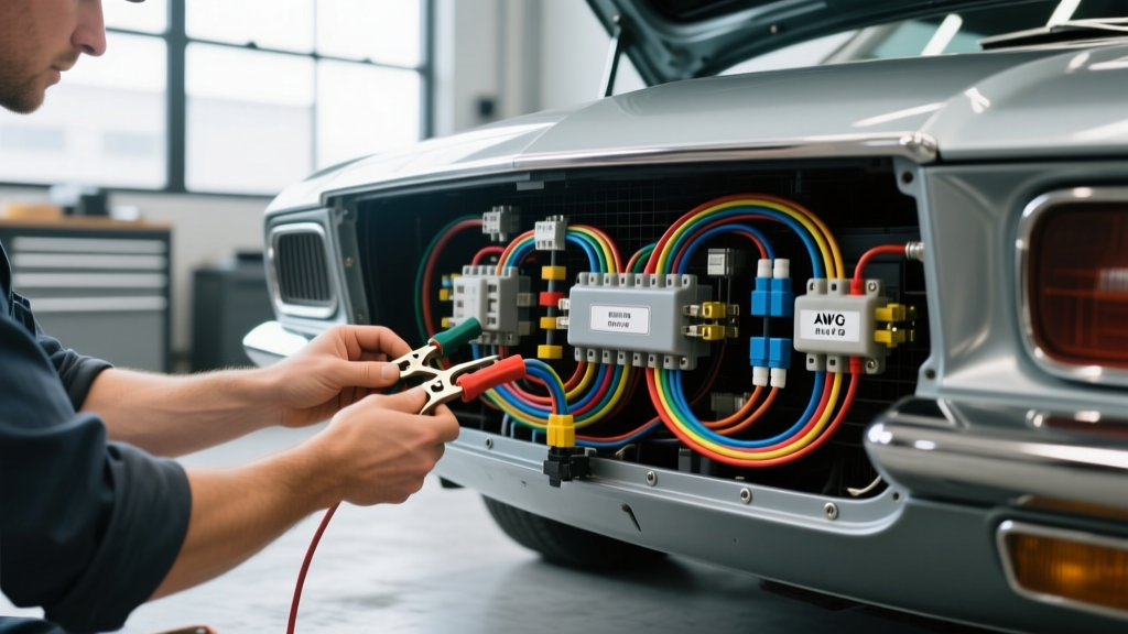
Introduction to the Terry's Auto Electric Methodology
When veteran builders discuss the gold standard of custom hot rod and classic muscle car wiring, the Terry's Auto Electric methodology inevitably comes up. Rewiring a classic vehicle requires far more than just zip-tying a universal kit under the dash and hoping for the best. The Terry's Auto Electric approach prioritizes OEM-level reliability, meticulous circuit segregation, aerospace-grade termination, and rigorous voltage drop testing. Whether you are installing a 21-circuit Painless Performance kit or an American Autowire Classic Update harness, following this practical how-to installation guide will ensure your vehicle's electrical architecture is safe, serviceable, and capable of handling modern high-draw accessories like dual electric cooling fans, fuel injection systems, and high-torque mini starters.
Universal wiring kits provide the raw materials, but the execution determines the reliability. This guide breaks down the professional installation techniques that separate a dangerous fire hazard from a concours-quality, bulletproof electrical system.
Phase 1: Essential Tooling and Material Selection
You cannot achieve professional-grade terminations with generic hardware store pliers. The Terry's Auto Electric standard mandates the use of precision ratcheting crimpers and automotive-grade wire. Avoid generic PVC wire; instead, source cross-linked polyethylene (XLPE) wire, specifically GXL or TXL, which meets SAE J1128 specifications for high-temperature engine bay environments.
- Wire Strippers: Precision gauge strippers (e.g., Knoweasy or Klein Tools) to avoid nicking copper strands.
- Crimpers: Ratcheting open-barrel crimpers for Molex/Deutsch pins, and dedicated Delphi Weather Pack crimpers for sealed engine bay connectors.
- Heat Shrink: Marine-grade, dual-wall adhesive-lined heat shrink (3:1 shrink ratio) to prevent moisture wicking.
- Loom & Tape: Split corrugated loom for interior cabins, and Tesa 51036 PET cloth tape for engine bay harness wrapping to resist heat and abrasion.
- Dielectric Grease: Nyogel 760G or equivalent for all sealed connector cavities.
Phase 2: Circuit Planning and AWG Sizing Matrix
Improper American Wire Gauge (AWG) sizing is the leading cause of melted bulkhead connectors and dim headlights in classic cars. Voltage drop over distance requires upsizing wires for long runs, particularly in front-engine vehicles where the battery is relocated to the trunk. Below is the standard circuit matrix utilized in high-end custom installations.
| Circuit Function | Wire Gauge (AWG) | Max Fuse Rating | Standard Wire Color | Connector Type |
|---|---|---|---|---|
| Main Battery Feed | 4 AWG or 2 AWG | 150A Mega Fuse | Red | Ring Terminal (5/16') |
| Alternator Output (1-Wire) | 8 AWG or 6 AWG | 100A Fusible Link | Red | Ring Terminal (5/16') |
| Headlight High/Low Beam | 14 AWG | 15A ATO | Green (High) / Yellow (Low) | Weather-Pack 2-Pin |
| Electric Cooling Fan (Dual) | 10 AWG | 30A ATO | Blue | Weather-Pack 2-Pin |
| Ignition Switch Feed | 10 AWG | 20A ATO | Pink | Bulkhead Spade |
| Tail / Parking Lights | 16 AWG | 10A ATO | Brown | Standard Spade / Socket |
Note: Always consult your specific harness manufacturer's manual, as color codes can vary between brands like Painless, Centech, and American Autowire.
Phase 3: Main Harness Routing and Firewall Penetration
The physical routing of the harness dictates its lifespan. Vibration, heat, and sharp sheet metal are the enemies of automotive wiring. Follow these numbered steps for a flawless engine-to-cabin transition:
- Firewall Preparation: Never drill a raw hole and push wires through. Install a dedicated, stepped rubber firewall grommet. Lubricate the inside of the grommet and the wire loom with a silicone-based dielectric grease to prevent the sheath from tearing during installation.
- Steering Column Clearance: Maintain a minimum 3-inch clearance between the wiring harness and the steering shaft U-joints. Secure the harness to the underside of the dash using aluminum Adel clamps (P-clips) with rubber cushions, avoiding sharp self-tapping screws near the loom.
- Engine Bay Heat Management: Route the harness along the inner fender wells, never across the top of the intake manifold or near exhaust headers. If crossing near an exhaust component is unavoidable, use a flexible fiberglass heat sleeve and maintain at least a 6-inch gap.
- The Drip Loop Rule: Before any wire enters a switch, relay, or bulkhead connector from below, create a downward 'U' shape (drip loop). This ensures that water running down the wire drips off the bottom of the loop rather than wicking directly into the electrical cavity.
Phase 4: Termination Standards and Crimping Dynamics
The most heavily debated topic in auto electrical work is soldering versus crimping. The Terry's Auto Electric methodology strictly forbids soldering wires that are subject to vibration (such as engine harnesses or door jambs). Solder wicks into the wire strands via capillary action, creating a rigid, brittle point just above the joint. Under constant engine vibration, this stiff section acts as a fulcrum, leading to copper fatigue and eventual wire breakage.
Instead, use ratcheting open-barrel crimpers. A proper crimp creates a cold-weld between the copper strands and the terminal barrel, maintaining strand flexibility. After crimping a Weather-Pack terminal, perform a pull-test: the wire should fail (break) before the crimp slips. Always apply dual-wall adhesive heat shrink over non-sealed spade and ring terminals to block oxygen and prevent copper oxidation.
Phase 5: Grounding Strategy and Power Distribution
According to experts at Mad Electrical, over 70% of classic car electrical gremlins (dim lights, erratic gauges, slow cranking) are caused by poor grounding. Do not rely on the rusty, painted sheet metal of a 50-year-old chassis to complete your circuits.
The Star Grounding Method
Instead of daisy-chaining grounds from one component to the next, utilize a centralized 'Star Ground' system. Mount a heavy-duty brass or copper grounding bus bar in the engine bay and another under the dash. Run individual ground wires from each component (headlights, ECU, fuel pump) back to the bus bar. From the bus bar, run a single, massive 4 AWG ground strap directly to a cleaned, bare-metal point on the engine block or chassis.
Torque Specifications for Grounds:
- Engine Block to Chassis Strap: 25-30 ft-lbs (ensure paint is sanded away to bare metal, then coat with clear nail polish or di-electric grease to prevent rust).
- Battery Terminal Clamps: 12-15 ft-lbs. Over-tightening lead post clamps will distort the lead and cause a high-resistance connection.
Phase 6: Fusing and Power Distribution Architecture
The main power feed from the battery must be protected immediately. Install a 150-Amp Marine Mega Fuse within 18 inches of the positive battery terminal. This protects the main 4 AWG cable in the event of a dead short against the chassis. From the main fuse, route power to a centralized under-hood power distribution block. From this block, feed the individual fused circuits (using standard ATO blade fuses) to their respective relays and switches. Never route unfused battery voltage into the cabin of the vehicle.
Phase 7: Pre-Flight Voltage Drop Testing
Before reinstalling interior trim panels or firing the engine, you must validate your connections. As outlined in standard diagnostic procedures by AA1Car, a continuity test is not enough; a wire with only two strands of copper intact will show continuity but will fail under load. You must perform a Voltage Drop Test.
How to Perform the Test:
- Set your digital multimeter to DC Volts.
- Connect the red probe to the positive battery post and the black probe to the component's positive terminal (with the circuit turned ON and under load).
- A healthy circuit should show a voltage drop of less than 0.1V (100mV) per connection or wire segment.
- If you read 0.5V or higher, you have high resistance caused by a loose crimp, corrosion, or undersized wire. Disassemble and repair immediately.
Real-World Failure Modes and Troubleshooting
Even with meticulous installation, issues can arise. Use this decision tree to diagnose common custom harness failures:
- Symptom: Headlights dim when the electric cooling fan kicks on.
Cause: Shared ground path or undersized alternator output wire.
Fix: Verify the fan relay is grounded directly to the engine block, not the radiator support. Upgrade alternator output wire to 6 AWG. - Symptom: Starter solenoid clicks rapidly but engine won't turn over.
Cause: Voltage drop across the ignition switch or neutral safety switch.
Fix: Install a Ford-style starter solenoid relay in the engine bay to carry the high-amperage load, using the ignition switch only to trigger the relay's low-amp coil. - Symptom: Melted bulkhead connector pins.
Cause: Terminal oxidation causing localized heat buildup, or using standard spade terminals for high-draw circuits like the blower motor.
Fix: Replace standard spades with high-current Weather-Pack or Metri-Pack sealed connectors, and apply conductive anti-oxidant paste.
By adhering to the Terry's Auto Electric methodology—prioritizing correct AWG sizing, ratcheting crimp tools, star-grounding, and rigorous voltage drop testing—you transform a universal wiring kit into a bespoke, reliable electrical system that will outlast the vehicle itself. Take your time, route cleanly, and never compromise on termination quality.