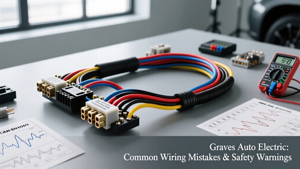
The Hidden Dangers of Improper Auto Electrical Work
Modern vehicle electrical architecture is a highly sensitive network of multiplexed data buses, high-amperage charging circuits, and precision sensors. When reviewing diagnostic case studies from high-volume specialists like Graves Auto Electric, a clear pattern of preventable electrical failures emerges. These failures rarely stem from factory defects; instead, they are the direct result of improper aftermarket installations, poor repair practices, and a fundamental misunderstanding of automotive DC circuit principles.
Electrical fires, parasitic draws that destroy new batteries, and erratic module behavior are the hallmarks of compromised wiring. This guide breaks down the most critical auto electrical mistakes documented in the field, providing actionable safety warnings, precise AWG specifications, and industry-standard correction protocols to ensure your vehicle's electrical system remains safe and reliable.
Mistake 1: The 'Ground Anywhere' Fallacy and Voltage Drops
The most pervasive error in general auto electrical repair is treating the vehicle chassis as an infinite, perfect ground sink. Many DIYers and general mechanics will ground high-draw accessories using self-tapping sheet metal screws into painted body panels. According to ASE A6 Certification Guidelines, a ground connection is only as good as its surface contact area and mechanical stability.
The Impact of Poor Grounding
Paint, powder coating, and rust act as dielectric insulators. When a high-amp circuit (like a fuel pump or cooling fan) relies on a compromised ground, it creates a high-resistance voltage drop. This forces the component to draw excess amperage to meet its wattage requirement (Watts = Volts x Amps), leading to melted harness connectors and premature motor failure.
The Correction Protocol
- Surface Preparation: Always use a wire wheel or sanding disc to remove all paint, primer, and e-coat down to bare, shiny metal.
- Hardware Selection: Use M8 or M10 factory ground studs. If a factory stud is unavailable, use a coarse-thread bolt with a DIN 6797 serrated star washer to bite through minor surface oxidation.
- AWG Specifications: Engine block to chassis grounds require a minimum of 4 AWG stranded copper. Body-to-engine grounds should be no smaller than 8 AWG.
- Corrosion Protection: Apply a dielectric grease or zinc-rich anti-corrosion compound only after the mechanical connection is torqued to spec.
Mistake 2: Alternator B+ Terminal Overloading
A frequent mistake seen in overlanding and off-road builds is wiring high-draw accessories directly to the alternator's B+ (Battery Positive) output terminal. While it seems logical to pull power straight from the source, the alternator's internal diode trio and stator windings are not designed to handle sudden, massive transient loads.
Diode Trio Burnout
Connecting a 2000W power inverter (which can pull over 160 Amps at 12V under load) directly to the alternator B+ post will instantly overwhelm the rectifier bridge. The diodes will overheat, short to ground, and potentially feed AC ripple voltage back into the vehicle's sensitive PCM and infotainment modules.
Safe High-Ampereage Routing
All high-draw aftermarket accessories must be wired directly to the battery positive terminal or a dedicated, properly fused mega-fuse distribution block. The alternator's job is to charge the battery; the battery's job is to buffer the transient loads. If you are upgrading to a high-output alternator (e.g., 250A+), the factory charge wire (usually 4 AWG or 2 AWG) must be upgraded to 1/0 AWG SAE J1128 GXL wire to prevent the charge wire from becoming a resistor and catching fire.
Mistake 3: High-Speed CAN-Bus Splicing Disasters
Modern vehicles rely on Controller Area Network (CAN) buses to transmit data between modules. High-speed CAN (often operating at 500 kbps) utilizes a twisted-pair architecture to reject electromagnetic interference (EMI). Tapping into these wires using 'Scotch-lock' connectors or stripping the twist to solder a pigtail is a catastrophic mistake.
Impedance Mismatch and Reflections
The CAN-Bus relies on a precise 120-ohm termination resistor at each end of the bus, creating a total parallel resistance of 60 ohms. Splicing into the wire alters the capacitance and destroys the physical twist rate, causing signal reflections and data packet collisions. This results in ghost codes, limp-mode activation, and U-codes (network communication faults).
Proper Diagnostic and Tapping Procedures
- Pin Configuration: On a standard OBD-II DLC, Pin 6 is CAN-High and Pin 14 is CAN-Low.
- Voltage States: In a recessive (idle) state, both CAN-H and CAN-L sit at approximately 2.5V. In a dominant (active) state, CAN-H rises to ~3.5V and CAN-L drops to ~1.5V.
- Wire Colors: Colors vary by manufacturer (e.g., GM often uses Tan/White and Tan/Black; Ford uses White and White/Purple). Never rely solely on color; always verify with an oscilloscope or digital multimeter.
- Connection Method: If a module must be added to the bus, use a proper CAN-bus breakout connector or a designated gateway module rather than piercing the factory harness insulation.
Mistake 4: Inadequate Overcurrent Protection and Fuse Placement
Running a 4 AWG power wire from the battery to an amplifier or winch solenoid without a fuse, or placing the fuse too far from the power source, is a leading cause of vehicle fires. If the wire chafes against the firewall before the fuse, the battery will dump its entire cold-cranking amp (CCA) capacity into a dead short, melting the wire insulation and igniting surrounding materials.
The 18-Inch Rule
Industry safety standards dictate that the primary overcurrent protection device (fuse or circuit breaker) must be installed within 18 inches of the battery positive terminal, measured along the wire path. For high-amperage circuits (100A - 300A), use ANL or Class T fuses. Standard AGU or Maxi fuses are insufficient and prone to internal arcing at high DC voltages.
Mistake 5: Soldering vs. Crimping in Automotive Environments
While soldering is standard in household electronics and PCB repair, it is heavily discouraged in automotive wiring harnesses. Solder wicks heat, which can melt adjacent wire insulation. More importantly, solder creates a rigid, brittle connection. The constant vibration and thermal cycling of an engine bay will cause soldered joints to fatigue, crack, and eventually fail, leading to high resistance or open circuits.
The SAE J1128 Standard and OEM harness manufacturers utilize open-barrel or closed-barrel mechanical crimps. A properly executed crimp using a ratcheting crimper creates a cold-weld gas-tight seal that is both electrically conductive and mechanically flexible, allowing it to withstand engine harmonics without fracturing.
Graves Auto Electric Safety & Specification Matrix
The following matrix outlines the strict specifications required to avoid the most common electrical hazards documented by top-tier diagnostic clinics.
| Circuit Type | Common Mistake | Proper Specification & Safety Rule |
|---|---|---|
| Engine Ground | Using 10 AWG wire to sheet metal | 4 AWG or 2 AWG to bare metal block using M10 stud & star washer |
| Alternator B+ Charge | Reusing factory 4 AWG on 250A alternator | Upgrade to 1/0 AWG GXL/TXL; Torque M8 nut to 12-15 Nm |
| Starter Positive | Ignoring voltage drop under load | Max 0.5V total drop across entire positive and ground path during crank |
| Main Battery Feed | Fusing at the distribution block | Class T or ANL fuse mounted within 18 inches of battery positive |
| CAN-Bus Network | Scotch-lock splicing / untwisting pair | Maintain 120-ohm termination; use OEM breakout connectors or gateway |
Essential Safety Protocols Before Cutting or Splicing
Before performing any electrical modification or diagnostic test, adhere to these non-negotiable safety protocols:
- Disconnect the Battery: Always disconnect the negative (-) terminal first, and reconnect it last. This prevents accidental shorting to the chassis while working on the positive side.
- Airbag System Warning: If working near the steering column, kick panels, or A-pillars, disconnect the battery and wait a minimum of 15 minutes for the Supplemental Restraint System (SRS) backup capacitors to discharge. Probing an airbag squib circuit with a multimeter's internal battery can inadvertently deploy the airbag.
- Use the Right Wire Type: Never use household PVC THHN wire. Automotive environments require cross-linked polyethylene insulation (GXL, TXL, or SXL) which resists high temperatures, fuel, and oil exposure, as outlined by Bosch Automotive Technology standards.
- Seal All Connections: Use dual-wall, adhesive-lined heat shrink tubing on all crimp connections. The inner layer of hot-melt adhesive creates a waterproof seal that prevents capillary action from drawing moisture into the copper strands.
By respecting the physics of DC circuits and adhering to the rigorous standards championed by diagnostic experts, you can eliminate the risk of electrical fires, module damage, and intermittent gremlins that plague poorly wired vehicles.