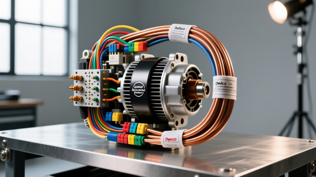
Advanced Integration of United Auto Electric Components
When upgrading, rebuilding, or replacing heavy-duty charging and cranking systems, technicians frequently turn to remanufactured and aftermarket components distributed by United Auto Electric. Known for supplying high-quality Delco Remy-style alternators and Denso-style Permanent Magnet Gear Reduction (PMGR) starters, these units are staples in both domestic and import vehicle electrical architectures. However, bolting on a new United Auto Electric alternator or starter is only half the battle. Modern vehicle electrical systems rely on complex Controller Area Network (CAN) bus topologies, Pulse Width Modulated (PCM) field control, and precise voltage sensing to manage electrical loads. Failing to properly integrate the wiring harness, verify pinout configurations, or perform SAE-standard voltage drop testing will result in chronic undercharging, parasitic draws, or premature diode bridge failure. This advanced technical guide provides a deep dive into the wiring architectures, diagnostic trees, and bench-testing protocols required for seamless United Auto Electric component integration.
Delco-Style Alternator Pinout and Exciter Circuit Wiring
Many of the domestic alternators supplied through United Auto Electric channels utilize the ubiquitous Delco CS130D or CS144 internal regulator architecture. These units utilize a 4-pin pigtail connector that interfaces directly with the Powertrain Control Module (PCM) or a standalone engine management system. Miswiring this connector is the leading cause of 'no-charge' conditions and blown PCM driver circuits.
CS130D / CS144 4-Pin Connector Specifications
| Pin | Designation | Wire Color (Typical GM) | AWG Size | Function & Integration Requirement |
|---|---|---|---|---|
| L | Lamp | Brown/White | 18 AWG | Provides initial 12V ignition-switched excitation. Must include a 56-ohm resistor or LED buffer in parallel to prevent back-feeding the PCM. |
| F | Field | Red/White | 18 AWG | PCM-controlled PWM signal. Operates at ~128 Hz with a 10% to 90% duty cycle to dictate target voltage based on calculated electrical load. |
| S | Sense | Orange | 10 AWG | Direct battery voltage feedback. Critical: Must be routed directly to the battery positive post or main fuse block. Never jumper S to the alternator B+ terminal. |
| P | Phase | Brown | 20 AWG | Stator tap providing an AC square wave signal. Used by the PCM to verify alternator rotation and drive the dashboard tachometer. |
The 'Sense' Circuit Fatal Flaw
A common installation error when integrating a United Auto Electric CS-series alternator into a custom harness or older classic car conversion is jumpering the 'S' (Sense) pin directly to the alternator's B+ output terminal. Because the alternator measures voltage at its own output post rather than at the battery, it cannot account for the voltage drop across the charging wire and battery cables. If the battery requires 14.2V, but there is a 0.8V drop across the harness, the alternator will only output 13.4V to the battery, resulting in a chronic state of undercharge and sulfation. Always route a dedicated 10 AWG sense wire from the 'S' pin directly to the battery positive terminal, protected by a 15A inline maxi-fuse located within 6 inches of the battery post.
Gear-Reduction Starter Solenoid Integration
United Auto Electric frequently supplies PMGR (Permanent Magnet Gear Reduction) starters, particularly Denso-style units used in high-compression and import applications. These starters utilize a two-terminal solenoid cap that requires distinct wiring protocols compared to older direct-drive Delco starters.
- S-Terminal (Start Signal): This spade terminal receives the 12V crank signal from the starter relay or ignition switch. It requires a minimum of 10.5V under load to overcome the solenoid return spring and engage the pinion gear. Use 10 AWG stranded copper wire for this circuit to prevent voltage drop during high-amp cranking events.
- M-Terminal (Motor Feed): This is the heavy-duty post connecting the solenoid to the starter motor internals. When replacing the battery-to-starter cable, use a minimum of 2 AWG welding cable for runs under 6 feet, and 1/0 AWG for longer routing paths. Torque the M-terminal nut to 12-15 Nm; over-torquing will crack the internal Bakelite insulator and cause a dead short to the starter housing.
- Bypass / 'R' Terminal: Older points-style ignition systems utilized an 'R' terminal to bypass the ballast resistor during cranking. Modern EFI systems and United Auto Electric PMGR units do not require this. If your replacement starter features an 'R' terminal, tape it off and secure it to prevent accidental grounding against the engine block.
SAE Voltage Drop Diagnostic Decision Tree
Before condemning a newly installed United Auto Electric starter or alternator, technicians must perform a voltage drop test according to SAE J1493 standards. A starter drawing 300 amps will generate significant heat in a high-resistance circuit, mimicking a failed component.
- Step 1: Positive Side Cranking Drop. Place the positive multimeter probe on the alternator B+ post (or battery positive) and the negative probe on the starter M-terminal. Crank the engine. Specification: Maximum 0.5V drop. If >0.5V, inspect battery cable crimps, underhood fuse block busbars, and ground eyelets.
- Step 2: Negative Side Cranking Drop. Place the positive probe on the starter motor housing (bare metal) and the negative probe on the battery negative post. Crank the engine. Specification: Maximum 0.2V drop. If >0.2V, clean the engine-to-chassis ground straps and apply dielectric grease.
- Step 3: Control Circuit Drop. Back-probe the starter relay output wire and measure against the starter S-terminal during the 'Start' key position. Specification: Maximum 0.1V drop. High resistance here indicates corroded ignition switch contacts or undersized relay wiring.
Bench Testing and AC Ripple Diagnostics
When evaluating a United Auto Electric alternator for internal diode trio failure, an AC Ripple test is vastly superior to a simple DC voltage check. The internal rectifier bridge converts the 3-phase AC stator output into DC. If a single diode fails open or shorted, the alternator will still produce 14V DC at idle, but will dump raw AC voltage into the vehicle's electrical system, causing CAN-bus communication faults and premature battery boiling.
AC Ripple Testing Protocol
Set your digital multimeter to AC Voltage (V~). Connect the probes directly to the alternator B+ terminal and the alternator rear housing ground. Rev the engine to 2,000 RPM and engage all major electrical loads (HVAC blower on high, headlamps on, rear defroster active). According to rigorous aftermarket testing standards documented by resources like AA1Car's Alternator Testing Library, the maximum allowable AC ripple voltage is 100mV (0.100V AC). If your multimeter reads 0.250V AC or higher, the internal rectifier bridge has suffered thermal failure, and the unit must be rebuilt or replaced.
Thermal Management and Torque Specifications
Heat is the primary enemy of automotive electrical components. When installing high-amp United Auto Electric alternators (140A+), ensure the rear cooling fins are not obstructed by aftermarket exhaust headers or power steering lines. The internal voltage regulator relies on conductive cooling through the alternator housing. Furthermore, when terminating the main B+ charging wire, always use a closed-loop ring terminal crimped with a hex-crimp die, followed by adhesive-lined heat shrink. The B+ terminal nut (typically M8 or 5/16-18 thread) must be torqued precisely to 12-15 Nm (9-11 lb-ft). Under-torquing creates micro-arcing that melts the plastic rear cover, while over-torquing strips the aluminum threads on the rectifier bridge assembly.
Summary of Best Practices
Integrating United Auto Electric components requires a methodical approach to wiring architecture, PCM signal verification, and SAE-compliant diagnostic testing. By respecting the specific AWG requirements for sense and exciter circuits, properly routing PMGR solenoid feeds, and utilizing AC ripple diagnostics, technicians can ensure maximum longevity and optimal electrical system performance across any vehicle platform.