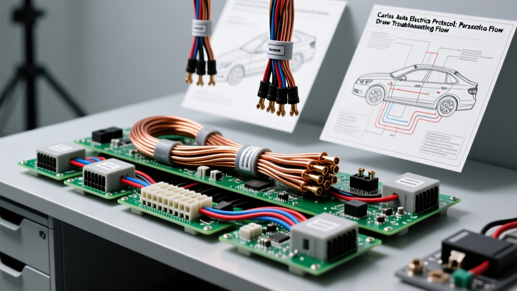
The Carlos Auto Electrics Methodology: Beyond the Multimeter
Modern vehicle electrical architectures rely heavily on multiplexed networks, LIN-bus subnets, and high-speed CAN-bus systems. When diagnosing a parasitic battery drain on a late-model vehicle, the traditional method of pulling fuses one by one is not only obsolete—it is actively counterproductive. Removing a fuse interrupts the circuit, which often forces a sleeping Body Control Module (BCM) or Gateway module to wake up, thereby masking the true parasitic draw. The Carlos Auto Electrics diagnostic protocol addresses this by utilizing a non-intrusive, step-by-step troubleshooting flow centered on voltage drop testing and network topology analysis. This guide details the exact procedures, wire gauge specifications, and pinout configurations required to execute this methodology effectively.
Phase 1: Non-Intrusive Shunt Preparation
The foundation of the Carlos Auto Electrics protocol is establishing a stable ammeter connection without ever breaking the primary battery circuit after the initial setup. Breaking the circuit causes a voltage spike that wakes up dormant modules, resetting the vehicle's sleep timer (which can take anywhere from 20 to 45 minutes on modern platforms).
Required Materials and Specifications
- Shunt Wire: 10 AWG stranded copper wire (rated for 600V, THHN/THWN). Do not use 12 AWG or smaller, as the resistance will alter the voltage drop calculations and potentially overheat during high-current crank tests if left connected.
- Terminals: Heavy-duty 10 AWG ring terminals, crimped with a hex-crimp tool and sealed with dual-wall adhesive heat shrink.
- Protection: 50A Maxi fuse in an inline waterproof holder, integrated into the 10 AWG shunt wire to protect the multimeter and vehicle wiring in the event of an accidental engine crank.
- Multimeter: A True-RMS digital multimeter capable of reading millivolts (mV) DC to at least three decimal places.
The Setup Procedure
- Disconnect the negative battery terminal.
- Connect one end of your 10 AWG shunt wire to the negative battery post, and the other end to the disconnected negative cable clamp.
- Reconnect the negative battery terminal through your shunt wire setup. The vehicle now has a continuous ground path.
- Connect your multimeter's 10A amperage port across the 50A Maxi fuse (or use a dedicated low-amp clamp meter zeroed out on the shunt wire) to monitor the initial high current as modules boot.
- Lock the vehicle using the mechanical key cylinder or a simulated door latch tool to ensure the BCM registers all doors as closed without triggering the interior courtesy lights.
- Wait for the vehicle's sleep cycle to complete. On most CAN-bus architectures, this takes 30 to 45 minutes. Target sleep current should drop below 50mA (0.050A).
Phase 2: The Voltage Drop Diagnostic Flow
If the ammeter reads a parasitic draw exceeding 50mA after the sleep cycle, the Carlos Auto Electrics protocol dictates moving to the Fuse Voltage Drop Test. Instead of pulling fuses, you will measure the millivolt (mV) drop across the exposed test points on the top of each fuse. Because every fuse acts as a low-value shunt resistor, the voltage drop across it is directly proportional to the current flowing through it.
Fuse Voltage Drop to Amperage Conversion Chart
Use the following reference table to convert your multimeter's millivolt reading into approximate amperage. Note that values can vary slightly based on fuse manufacturer and ambient temperature, but this chart provides a highly accurate baseline for ATO and Mini fuses.
| Fuse Type | Rating | mV Drop per 100mA | mV Drop per 1A | Typical Circuit Application |
|---|---|---|---|---|
| ATO (Standard) | 10A | 1.40 mV | 14.0 mV | Radio, Cigar Lighter, BCM Ignition |
| ATO (Standard) | 15A | 0.95 mV | 9.5 mV | Hazards, Horn, Power Mirrors |
| ATO (Standard) | 20A | 0.70 mV | 7.0 mV | Power Seats, Sunroof, ABS Valves |
| Mini | 10A | 1.80 mV | 18.0 mV | TCM, Gateway Module, OBD2 DLC |
| Mini | 15A | 1.20 mV | 12.0 mV | Fuel Pump Relay, Injectors |
| Low-Profile Mini | 20A | 0.85 mV | 8.5 mV | HVAC Blower, Heated Seats |
Diagnostic Tip: If you measure a 14.0 mV drop across a 10A ATO fuse, you have exactly 1.0 Amp (1000mA) of continuous draw on that circuit. Isolate the components on that specific wiring diagram branch to find the culprit.
Phase 3: CAN-Bus and Multiplex Wake Faults
A common failure mode identified in the Carlos Auto Electrics workflow is the 'Wake Fault,' where an aftermarket device or a failing module continuously broadcasts on the CAN-bus, preventing the network from going to sleep. To diagnose this, you must interrogate the Data Link Connector (DLC / OBD2 port).
OBD2 Pinout and Network Topology
- Pin 6 (CAN High): High-speed CAN bus. Typically operates between 2.5V and 3.5V. Wire color is often a twisted pair, such as White/Blue (Ford) or Dark Green (GM).
- Pin 14 (CAN Low): High-speed CAN bus. Operates between 1.5V and 2.5V. Twisted pair mate to Pin 6.
- Pin 3 & Pin 11 (MS-CAN): Medium-speed CAN (often used for body/comfort modules on Ford/GM). If an aftermarket alarm is improperly spliced into the MS-CAN network, it will cause a continuous wake state.
Testing Terminating Resistors
With the vehicle asleep and the battery disconnected (or using a breakout box to avoid waking the network), measure the resistance between Pin 6 and Pin 14. You should read exactly 60 Ohms. This indicates that the two 120-Ohm terminating resistors (usually located in the BCM and the PCM) are in parallel and intact. If you read 120 Ohms, one module is missing or a wire is broken. If you read 0-10 Ohms, the CAN High and CAN Low wires are shorted together, which will cause a massive parasitic draw as modules frantically attempt to re-establish network communication.
Phase 4: Symptom-Cause-Fix Decision Matrix
Use this troubleshooting decision tree to rapidly isolate the root cause of the parasitic draw based on your Phase 2 and Phase 3 findings.
| Symptom / Measurement | Probable Cause | Carlos Auto Electrics Fix Protocol |
|---|---|---|
| Draw drops to 0mA when pulling the OBD2 / DLC Mini fuse. | Aftermarket insurance tracker, telematics dongle, or faulty OBD2 scanner left in the port. | Remove aftermarket DLC devices. Inspect DLC Pin 16 (Constant 12V) for back-fed voltage from a pinched harness. |
| Draw remains at 400mA; CAN H/L resistance reads 120 Ohms. | Open circuit in CAN-bus wiring; Gateway module stays awake searching for the missing node. | Locate the open 120-Ohm terminating resistor. Check the BCM/PCM connector for backed-out pins or corroded CAN splices in the kick panel. |
| Draw spikes to 2A every 45 seconds, then drops to 100mA. | Aftermarket alarm system polling door pin switches or a failing Bluetooth/Telematics antenna module. | Disconnect the aftermarket alarm brain. If OEM, check the Telematics/OnStar module in the trunk or rear headliner for water intrusion. |
| High mV drop across the HVAC / Blower Motor 20A ATO fuse. | Blower motor resistor block shorted, or water ingress into the cabin blower motor causing a high-resistance ground path. | Inspect the HVAC case drain for clogs. Test blower motor amp draw independently using a 10 AWG jumper and inline 30A fuse. |
Conclusion and Best Practices
The Carlos Auto Electrics protocol emphasizes patience and precision. By utilizing a 10 AWG non-intrusive shunt and relying on millivolt drop calculations across standard fuses, you eliminate the risk of resetting module sleep timers. Always verify your multimeter's zero-offset before testing, and ensure your probe tips are sharp enough to pierce surface oxidation on fuse test points. For further reading on network topologies and standard testing procedures, consult the authoritative resources below.