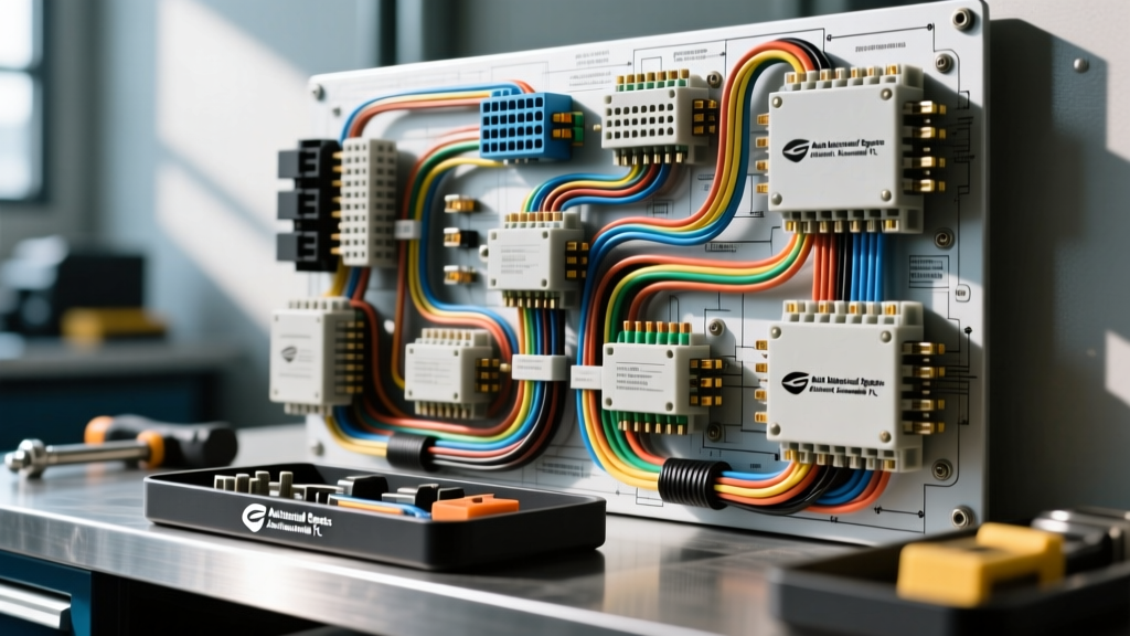
Benchmarking Heavy-Duty Auto Electrical Standards
When evaluating top-tier regional benchmarks for commercial, marine, and heavy-duty vehicle electrical systems, the technical standards upheld by specialists like Arlington Auto Electric in Jacksonville, FL, provide an exceptional framework for technicians nationwide. Operating in a high-humidity, coastal, and heavy-commercial corridor requires strict adherence to advanced wiring protocols that far exceed standard passenger vehicle specifications. Whether dealing with high-output alternator upgrades, salt-air corrosion mitigation, or heavy-duty starter circuit diagnostics, understanding these rigorous technical specifications is vital for any automotive electrical engineer or master technician.
This technical reference guide breaks down the exact wiring architectures, AWG sizing matrices, and diagnostic pinouts required to maintain reliability in extreme environments. By applying these commercial and marine-grade standards, you can ensure that high-amp electrical systems operate without voltage drop, thermal runaway, or galvanic corrosion.
High-Output Alternator Upgrade Specifications
Upgrading from a stock 140A alternator to a 250A or 320A high-output unit is common in commercial work trucks, overland rigs, and marine vessels. However, pushing this amperage through factory wiring harnesses will result in catastrophic voltage drop and potential electrical fires. The benchmark for these upgrades requires bypassing the factory harness and running dedicated, properly fused heavy-gauge cables directly from the alternator B+ terminal to the battery bank.
For high-amperage runs, standard SAE J1128 automotive wire is insufficient due to its thicker insulation and lower strand count. Instead, technicians must use fine-strand welding cable or marine-grade tinned copper. For example, a 1/0 AWG premium welding cable contains approximately 1,332 strands of 30 AWG copper, providing superior flexibility and lower DC resistance compared to standard battery cables. When terminating these cables, a 12-ton hydraulic crimper must be used with heavy-duty 3/8-inch closed-loop ring terminals, followed by sealing with dual-wall adhesive heat shrink.
Alternator Output vs. Cable Size Matrix
The following matrix dictates the minimum cable requirements based on alternator output and standard 10-foot cable runs. Fusing must always be installed within 18 inches of the battery positive terminal to protect the un-fused run.
| Alternator Output (A) | Min AWG (Cable) | Fuse Rating (Class T) | Max Run Length (ft) | Terminal Torque Spec |
|---|---|---|---|---|
| 140A | 4 AWG | 175A | 10 ft | 10-12 Nm (M8 Nut) |
| 200A | 2 AWG | 250A | 10 ft | 12-15 Nm (M8 Nut) |
| 250A | 1/0 AWG | 300A | 12 ft | 12-15 Nm (M8 Nut) |
| 320A | 2/0 AWG | 400A | 12 ft | 15-18 Nm (5/16" Nut) |
According to SAE J1128 guidelines for low-tension primary cable, any run exceeding 12 feet requires stepping up one AWG size to compensate for increased resistance and maintain a voltage drop below 0.5V at maximum load.
Marine-Grade Wiring Protocols for Coastal Environments
The coastal humidity and salt-air exposure inherent to the Jacksonville, FL region demand strict adherence to marine electrical standards. Standard untinned automotive copper wire will rapidly oxidize in these conditions, leading to blackened wire strands, increased resistance, and eventual circuit failure. To combat this, all wiring exposed to the elements or routed through bilges and engine bays must comply with ABYC E-11 Marine Electrical Standards.
UL 1426 Tinned Copper vs. SAE J1128
Marine-grade wire (UL 1426) features individually tinned copper strands. The tin coating acts as a sacrificial barrier against galvanic corrosion and salt-air oxidation. Furthermore, UL 1426 wire utilizes a PVC insulation jacket that is resistant to oil, gasoline, and extreme heat (rated up to 105°C). When terminating UL 1426 wire, technicians must avoid standard nylon-insulated crimps. Instead, use un-insulated copper lugs covered by 3:1 shrink ratio, dual-wall polyolefin heat shrink tubing. The internal thermoplastic adhesive layer melts during the shrinking process, creating a watertight seal that prevents moisture from wicking into the copper strands via capillary action.
Voltage Drop Calculation in Corrosive Environments
Corrosion increases circuit resistance, which directly correlates to voltage drop. The formula for calculating voltage drop in a DC circuit is:
VD = (2 × K × I × L) / A
- VD: Voltage Drop
- K: Resistivity of copper (approx. 12.9 ohms per mil-foot at 75°C)
- I: Current in Amps
- L: One-way length of the wire in feet
- A: Cross-sectional area of the wire in circular mils
In coastal environments, if a connection is not properly sealed, the effective cross-sectional area (A) decreases as corrosion eats away at the copper strands, exponentially increasing the voltage drop and generating dangerous heat at the terminal.
Heavy-Duty Starter Circuit Pinouts and Diagnostics
Commercial vehicles and marine diesels frequently utilize heavy-duty starters such as the Delco Remy 39MT or 42MT series. Diagnosing crank-no-start conditions or slow-cranking issues requires a methodical voltage drop test across the entire starter circuit, referencing Delco Remy Heavy Duty Service Manuals. A healthy starter circuit should exhibit a maximum total voltage drop of 0.5V across the positive and negative sides combined during cranking.
Delco Remy 39MT/42MT Starter Terminal Specifications
- Terminal B+ (Battery Positive): 3/8"-16 threaded stud. Requires 2/0 AWG or 1/0 AWG cable depending on run length. Torque spec: 25-30 Nm. Wire color: Typically Red with heavy-duty adhesive heat shrink.
- Terminal S (Start Signal): 10-32 threaded spade or ring terminal. Requires 10 AWG or 12 AWG wire. Carries the solenoid engagement current (usually 10-15A). Wire color: Typically Purple or Yellow/Red. Voltage drop limit: 0.2V max.
- Terminal R (Run/Ignition Bypass): 10-32 threaded spade. Used to provide a 12V bypass signal to the ignition coil or ECU during cranking. Wire color: Typically Yellow. Note: Many modern heavy-duty applications leave this terminal unpopulated as the ECU manages fuel/spark timing independently of the starter solenoid.
- Ground Path: The starter grounds through its mounting flange to the engine block. The block must have a dedicated 2/0 AWG ground strap connecting it to the battery negative or chassis ground bus. Torque starter mounting bolts to 100-120 Nm to ensure a solid ground path.
Voltage Drop Decision Tree
- Test 1 (Positive Side): Place multimeter positive lead on Battery B+ and negative lead on Starter B+. Crank engine. If reading > 0.3V, inspect battery cables, isolation switches, and manual disconnects for corrosion or loose crimps.
- Test 2 (Negative Side): Place multimeter negative lead on Battery Negative and positive lead on Starter Housing (not the engine block). Crank engine. If reading > 0.2V, the engine ground strap is compromised or the starter mounting flange is corroded.
- Test 3 (Control Circuit): Place leads across the ignition switch output and the Starter 'S' terminal. Crank engine. If reading > 0.5V, the cab wiring harness or starter relay contacts are degraded.
Auxiliary Electric AC Compressor Architecture
For heavy-duty trucks, auxiliary power units (APUs), and marine vessels, engine-driven AC compressors are often replaced or supplemented by high-output 12V or 24V electric AC compressors. These units draw significant continuous current (often 30A to 50A) and require dedicated relay-controlled circuits to prevent overloading the vehicle's primary accessory bus.
Electric Compressor Relay Pinout and Wiring
When wiring a heavy-duty 40A electric AC compressor, an ISO 280 heavy-duty relay or a solid-state contactor must be used. Standard 30A mini-relays will suffer from contact welding under the high inductive load of the compressor clutch and motor startup surge.
- Pin 30 (Power In): 8 AWG wire (Red) from a dedicated 50A circuit breaker tied directly to the battery bus.
- Pin 87 (Power Out): 8 AWG wire (Blue) to the electric compressor positive terminal.
- Pin 85 (Ground): 12 AWG wire (Black) to a verified clean chassis ground.
- Pin 86 (Trigger): 14 AWG wire (Green) from the dashboard HVAC control module or thermostat switch.
To suppress the inductive voltage spike generated when the compressor clutch disengages, a flyback diode (e.g., 1N5408) must be installed across the compressor coil terminals, with the cathode band facing the positive supply. Alternatively, a relay with an integrated suppression resistor should be utilized to protect the vehicle's sensitive CAN bus networks and HVAC control modules from electromagnetic interference (EMI).
Summary of Best Practices
Maintaining the rigorous standards expected of premier regional specialists like Arlington Auto Electric in Jacksonville, FL, requires moving beyond basic automotive wiring practices. By implementing UL 1426 marine-grade tinned wiring, strictly adhering to high-amp AWG matrices, executing precise voltage drop diagnostics on heavy-duty starter circuits, and properly architecting high-draw electric AC compressor systems, technicians can guarantee long-term reliability. Whether the vehicle is navigating coastal salt-air or enduring the heavy electrical loads of a commercial job site, these technical specifications form the bedrock of professional auto electrical engineering.