Mastering Connector Schematics in Automotive Wiring
When diagnosing modern vehicle networks, reading a wiring diagram goes far beyond simply following a line from point A to point B. The true complexity of automotive electrical systems lies in the interconnections—specifically, how to properly interpret auto electrical plugs on a schematic. Unlike basic point-to-point wiring, connector diagrams introduce cavities, terminal position assurances (TPA), mating face orientations, and specific wire gauge requirements. Misinterpreting a connector schematic is one of the most common causes of misdiagnosis, leading technicians to back-probe the wrong cavity or replace perfectly good components.
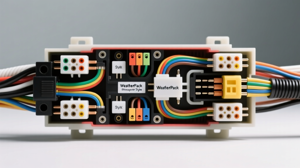
In this complete walkthrough, we will dissect a standard OEM wiring diagram featuring a 4-way Weather-Pack connector commonly used in powertrain control module (PCM) sensor circuits. By the end of this guide, you will understand how to translate a 2D schematic into a 3D physical diagnostic procedure, ensuring accurate multimeter testing and preventing terminal damage.
Understanding Diagram Conventions: Mating Face vs. Wire Entry
Before tracing any circuit, you must understand the perspective of the schematic. According to APTIV Connector Systems (formerly Delphi), OEM service manuals universally depict auto electrical plugs from the mating face perspective (the side that plugs into the component or opposing harness), even when illustrating the wire entry side. This convention ensures that a technician looking at the face of a disconnected plug can directly map the schematic to the physical cavities without mental mirroring.
On most factory diagrams, the connector is represented as a rectangle or a circle. The cavities are numbered or lettered sequentially. However, the physical layout rarely follows a simple left-to-right reading pattern. For example, a 4-way square Weather-Pack plug will have cavities labeled A, B, C, and D in a clockwise pattern starting from the top left, but the schematic may list them linearly based on circuit priority rather than physical geometry.
Step-by-Step Walkthrough: 4-Way MAP Sensor Circuit
Let us walk through a real-world diagnostic scenario: tracing a Manifold Absolute Pressure (MAP) sensor circuit utilizing a 4-way sealed connector. The schematic shows the PCM supplying a 5-volt reference, a low-level ground, and reading the analog signal return, with the fourth cavity serving as an Intake Air Temperature (IAT) signal return.
Step 1: Identifying the Power and Ground Reference
On the schematic, Cavity A is designated as the 5V Reference. The wire color is listed as Dark Green (DK GRN) with an 18 AWG rating. Following SAE J1128 standards for automotive primary wire, an 18 AWG GXL (cross-linked) wire is used here because the current draw of a MAP sensor reference circuit is typically under 50 milliamps. The diagram indicates a splice (S104) upstream, meaning this 5V reference is shared with the Throttle Position Sensor (TPS). If your multimeter reads 0V at Cavity A, the diagnostic tree must expand to include the TPS circuit to isolate the short to ground.
Step 2: Tracing the Signal Returns
Cavity B is the MAP Signal Return (Light Blue, 18 AWG). The schematic shows this wire routing directly to Pin 42 on the PCM's primary connector. Notice the shielded wire notation on the diagram—a dashed line surrounding the circuit path. This indicates that while the wire itself is 18 AWG, it is wrapped in a braided metallic shield to prevent Electromagnetic Interference (EMI) from the alternator and ignition coils. The shield is grounded at the PCM bracket, not inside the auto electrical plug itself.
Step 3: Component Ground vs. Chassis Ground
Cavity C is the Sensor Ground (Black, 18 AWG). It is critical to note that the diagram shows this wire routing back to a 'Signal Return' or 'Analog Ground' bus inside the PCM, rather than a chassis ground bolt. Testing this cavity with a test light to the battery positive will destroy the PCM's internal driver. You must use a high-impedance Digital Volt-Ohm Meter (DVOM) to verify continuity back to the PCM ground pin.
Pinout and Wire Color Reference Chart
| Cavity | Pin Name / Function | Wire Color | AWG Size | Terminal Type | Diagnostic Notes |
|---|---|---|---|---|---|
| A | 5V Reference (Shared) | DK GRN | 18 AWG GXL | Female Weather-Pack | Check for shared shorts at Splice S104 |
| B | MAP Signal Return | LT BLU | 18 AWG Shielded | Female Weather-Pack | Verify shield drain wire continuity to PCM |
| C | Sensor Low Reference | BLK | 18 AWG GXL | Female Weather-Pack | Do NOT test with a test light; use DVOM |
| D | IAT Signal Return | YEL/BLK | 20 AWG GXL | Female Weather-Pack | High resistance here causes false cold readings |
Advanced Tracing: Dealing with Secondary Locks and Seals
Wiring diagrams rarely show the physical locking mechanisms of auto electrical plugs, but they are vital to your physical walkthrough. The 4-way connector in our example utilizes a Terminal Position Assurance (TPA) lock. This is a secondary plastic comb that snaps over the back of the connector once the terminals are inserted. If a previous technician failed to seat the TPA, vibration will cause the terminal to back out, resulting in an intermittent open circuit that only occurs at specific RPMs.
Furthermore, the diagram will often feature a 'cavity plug' or 'dummy pin' notation if a specific vehicle trim level does not use all cavities. For instance, if the IAT sensor is integrated into the Mass Air Flow (MAF) sensor on a different engine variant, Cavity D will be shown with an 'X' or labeled as 'N/A'. Always cross-reference the RPO (Regular Production Option) codes or VIN-derived build sheet before assuming a cavity should have voltage.
Common Diagnostic Pitfalls with Auto Electrical Plugs
Even with a perfect understanding of the wiring diagram, physical inspection of the plugs can reveal issues the schematic cannot predict. Be on the lookout for these real-world failure modes:
- Fretting Corrosion: Tin-plated terminals (common in older GM and Ford applications) are prone to micro-movements that wear away the tin, exposing the base metal to oxidation. This creates a high-resistance voltage drop that mimics a failing sensor. Silver-plated terminals resist this but must never be mated with tin-plated opposing terminals due to galvanic corrosion.
- Back-Probing Damage: Forcing a standard multimeter probe into the back of a sealed weather-pack plug will permanently spread the terminal tangs. This ruins the tension of the female terminal, leading to future intermittent connection failures. Always use dedicated T-pin back-probes or break-out boxes.
- Dielectric Grease Misapplication: Applying dielectric grease to the terminal mating surfaces rather than the outer rubber weather seal can trap air and increase resistance in low-voltage signal circuits. Grease should only be applied to the silicone ribbed seals to prevent moisture ingress.
Conclusion
Successfully navigating auto electrical plugs requires a dual-threat approach: the ability to read OEM schematic logic and the physical dexterity to inspect, probe, and verify the connector hardware. By understanding mating face perspectives, respecting wire gauge and shielding notations, and identifying shared circuit splices, you can drastically reduce diagnostic time. Always rely on factory-accurated pinout tables and SAE-compliant testing procedures to ensure your electrical repairs stand the test of time and road vibration.