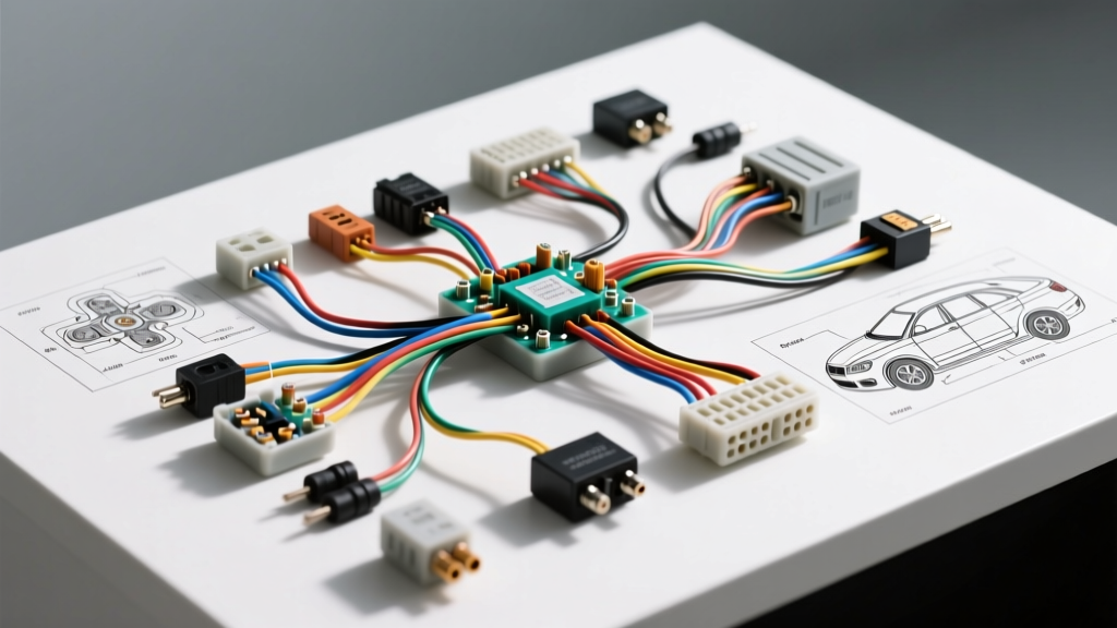
The Gold Standard: Learning from Hammett's Auto Electric
When classic car restorers, hotrod builders, and concours judges discuss automotive electrical reliability, the benchmark is often set by legendary specialty shops. The meticulous standards synonymous with Hammett's Auto Electric represent the pinnacle of harness fabrication, circuit protection, and gremlin-free diagnostics. In the professional realm, electrical work is not just about making a component turn on; it is about ensuring the circuit survives extreme under-hood temperatures, high-frequency vibrations, and moisture intrusion without becoming a fire hazard.
Unfortunately, the DIY automotive community is plagued by dangerous shortcuts. From twisted wire splices wrapped in cheap vinyl tape to improperly sized fuses that turn wiring harnesses into glowing heating elements, these mistakes lead to thousands of vehicle fires annually. To elevate your build from a rolling hazard to a reliable machine, we must dissect the most common automotive wiring mistakes and apply professional-grade safety warnings and corrections to your workflow.
The Twist-and-Tape Epidemic: Connector and Splice Failures
One of the most pervasive and dangerous mistakes in amateur automotive wiring is the twist-and-tape splice. Twisting two copper wires together and wrapping them in standard PVC electrical tape is a guaranteed failure point. Under-hood temperatures can exceed 120°C (248°F), causing the adhesive on cheap tape to melt, unravel, and expose bare copper to moisture and oxygen. This leads to rapid galvanic corrosion, increased resistance, localized heating, and eventually, an electrical fire.
Professional harness builders adhere to strict crimping and sealing standards. For chassis wiring, the correct method involves using adhesive-lined, dual-wall polyolefin heat shrink with a 3:1 shrink ratio. When heated, the outer wall shrinks tightly while the inner wall melts, creating a waterproof seal that blocks capillary action and prevents corrosion from wicking up the wire strands.
For high-vibration environments like engine bays or suspension-mounted sensors, soldering can actually be detrimental. Solder creates a rigid joint that can fatigue and crack under constant vibration. Instead, professionals use open-barrel crimp connectors with wire seals, or ruggedized circular connectors like the Deutsch DT Series. These connectors feature solid thermoplastic housings, silicone rear wire seals, and copper alloy contacts that maintain constant tension even under extreme engine harmonics.
Grounding Nightmares: Chassis vs. Dedicated Bus Bars
A floating ground or a high-resistance ground is the root cause of 80% of all automotive electrical gremlins. Dim headlights, erratic fuel pump behavior, and ECU sensor faults often trace back to a single, poorly executed ground connection. The most common DIY mistake is attaching a ground ring terminal directly over paint, powder coat, or rust, or relying on a single rusty chassis bolt to ground a high-draw component like a starter or electric cooling fan.
The professional approach requires dedicated grounding strategies. High-amperage components must be grounded directly to the engine block or chassis using heavy-gauge cable, and the mating surface must be stripped to bare, shiny metal. After torquing the fastener, the area must be coated with a conductive anti-oxidant paste to prevent future rust formation.
Grounding Specification Chart
| Fastener Size | Wire AWG | Ring Terminal Stud | Torque Spec | Surface Prep & Sealant |
|---|---|---|---|---|
| M6 (10mm Head) | 12 - 14 AWG | #10 / M5 | 7 - 10 Nm | Strip to bare metal, apply Noalox |
| M8 (13mm Head) | 8 - 10 AWG | 5/16' / M8 | 15 - 20 Nm | Strip to bare metal, apply Noalox |
| M10 (15mm Head) | 4 - 6 AWG | 3/8' / M10 | 25 - 35 Nm | Strip to bare metal, apply Noalox |
| M12 (17mm Head) | 1/0 - 2 AWG | 1/2' / M12 | 45 - 55 Nm | Strip to bare metal, apply Noalox |
For complex dashboards or modern ECU swaps, running individual ground wires to a centralized, heavy-gauge copper bus bar is the preferred method. This star-grounding technique prevents ground loops, where varying current draws from different components cause voltage fluctuations across shared ground paths.
Overfusing and the Penny in the Fuse Box Syndrome
When a fuse blows, it is communicating a critical message: the circuit is drawing more current than the wire can safely handle, or there is a dead short to ground. The amateur response is often to install a larger fuse to stop the nuisance blowing. This is a catastrophic safety violation. A fuse is not designed to protect the component; it is designed to protect the wire. If you place a 30A fuse on a circuit wired with 18 AWG wire, the wire will reach its melting point and catch fire long before the fuse blows.
Adhering to the SAE J1128 Low Tension Primary Cable Standard and cross-referencing with Littelfuse application guides ensures your wire gauge and fuse sizing are perfectly matched.
AWG to Fuse Sizing Reference (Automotive GXL/TXL Wire)
| Wire Gauge (AWG) | Max Continuous Ampacity | Recommended Max Fuse | Typical Application |
|---|---|---|---|
| 18 AWG | 10 Amps | 10A | ECU sensors, dash illumination, relays coils |
| 16 AWG | 13 Amps | 15A | Tail lights, horn, interior dome lights |
| 14 AWG | 18 Amps | 20A | Headlights, fuel pump, power windows |
| 12 AWG | 25 Amps | 25A / 30A | High-power cooling fans, heated seats, amplifiers |
| 10 AWG | 40 Amps | 40A | Main ignition feeds, high-draw auxiliary lighting |
Always use the correct fuse type for the application. Standard ATO/ATC blade fuses are suitable for general chassis wiring, but high-current under-hood applications require MIDI or MEGA fuses, while sensitive ECU circuits benefit from the fast-blow characteristics of Micro2 or Micro3 fuses.
Relay Wiring Blunders: Pin 87 vs. Pin 87a and Flyback Diodes
The Bosch-style ISO mini relay is the workhorse of automotive electrical systems, yet it is frequently miswired. A standard 5-pin relay features terminals labeled 30, 85, 86, 87, and 87a. The most common mistake is confusing Pin 87 (Normally Open) with Pin 87a (Normally Closed). Wiring a cooling fan to Pin 87a means the fan will run constantly when the key is off, and will shut off when the ECU triggers the relay—the exact opposite of the intended logic.
Standard ISO Mini Relay Pinout:
- Pin 30 (Common): High-current input from the battery (must be fused within 18 inches of the power source).
- Pin 85 (Coil Ground): Ground path for the internal electromagnet coil.
- Pin 86 (Coil Trigger): Low-current switched 12V+ from the dashboard switch or ECU.
- Pin 87 (Normally Open): High-current output to the load (e.g., fuel pump, fan). Only receives power when the relay is energized.
- Pin 87a (Normally Closed): Receives power when the relay is at rest. Used for specific logic circuits like alarm kill switches.
The Flyback Diode Warning: When a relay coil is de-energized, the collapsing magnetic field generates a massive reverse voltage spike (back-EMF) that can exceed 100 volts. If Pin 85 and 86 are triggered directly by a modern ECU or a sensitive solid-state switch, this spike will instantly destroy the internal driver transistor. To prevent this, professionals solder a 1N4004 flyback diode across the coil pins (Pin 85 and 86), with the diode's stripe facing the positive trigger side. This creates a safe recirculation loop for the voltage spike, protecting your expensive ECU.
Routing Hazards: Exhaust, Sharp Edges, and EMI
Even perfectly crimped and fused wiring will fail if routed improperly. Two major hazards exist in the under-hood environment: thermal degradation and Electromagnetic Interference (EMI).
Standard cross-linked polyethylene (GXL/TXL) wire insulation is rated for 125°C. However, exhaust manifolds and turbochargers routinely exceed 400°C. Wiring harnesses must maintain a minimum clearance of 6 inches from any exhaust component. If crossing an exhaust pipe is unavoidable, the wire must be routed inside a fiberglass firesleeve or corrugated nylon loom with high-temp aluminum backing.
EMI is the invisible killer of modern engine swaps. High-voltage ignition wires (spark plug leads) emit intense electromagnetic fields. If low-voltage sensor wires (like O2 sensors, MAP sensors, or crank position sensors) are routed parallel to ignition wires, the ECU will read the EMI as false sensor data, resulting in erratic timing, misfires, and limp-mode activation. Always route sensor wiring at a 90-degree angle to high-voltage ignition lines, and utilize shielded twisted-pair (STP) cables for critical data bus networks like CAN-High and CAN-Low, ensuring the shield drain wire is grounded at one end only to prevent ground loops.
Conclusion: Respect the Electrons
Adopting the rigorous standards championed by experts at Hammett's Auto Electric is not about pedantry; it is about survival and reliability. By eliminating twist-and-tape splices, calculating precise ground paths, matching wire gauges to fuse limits, and protecting sensitive triggers with flyback diodes, you transform a fragile DIY wiring job into a professional-grade electrical architecture. Respect the electrons, follow the SAE standards, and your vehicle will start, run, and stop safely for decades to come.