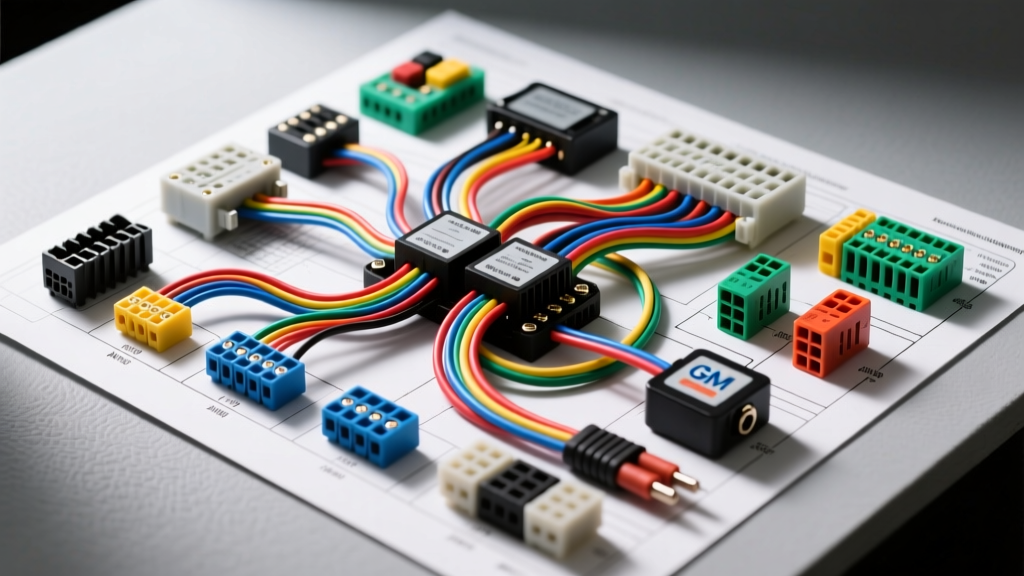
Introduction to the Freddy's Auto Electric Standard
When performing a complete wiring diagram walkthrough on a classic restomod, the margin for error is virtually zero. The Freddy's Auto Electric methodology has become a benchmark in the custom automotive electrical industry for translating complex, multi-circuit schematic diagrams into flawless, fire-safe, and reliable physical harnesses. Unlike factory wiring diagrams from the late 1960s and 1970s—which often relied on undersized gauge wiring and inadequate grounding through rust-prone chassis points—the Freddy's Auto Electric standard mandates modern relay integration, upgraded AWG (American Wire Gauge) sizing, and cross-linked polyethylene (XLPE) insulation.
In this comprehensive walkthrough, we will decode the Freddy's Auto Electric approach using a 1969 Chevrolet Camaro custom harness build as our reference model. We will trace the architecture from the main power distribution bulkhead, through the headlight relay integration, down to the GM 12-pin ignition switch mapping, and finally into the star-grounding network. By following these exact specifications, you can ensure your vehicle's electrical system meets modern SAE J1128 Low Tension Cable Standards while retaining OEM aesthetic routing.
Phase 1: Main Power Distribution and Bulkhead Routing
The foundation of any Freddy's Auto Electric diagram walkthrough begins at the main power distribution node. Classic GM vehicles originally routed the main alternator output and battery feeds through a flat, multi-pin bulkhead connector on the firewall. This design is notorious for voltage drop and thermal melting when paired with modern 100+ amp alternators.
The Freddy's Auto Electric protocol bypasses the factory bulkhead for high-amperage feeds. Instead, a dedicated firewall pass-through is utilized for the main power cables, sealed with dielectric grease and rubber grommets to prevent chafing against the sheet metal.
- Battery to Starter Solenoid: 2 AWG GXL (Cross-linked, thin-wall) copper wire. This heavy gauge prevents voltage drop during high-compression engine cranking, ensuring a minimum of 10.5V reaches the starter solenoid.
- Alternator BAT Post to Main Junction: 8 AWG GXL wire routed to a centralized, fused horn-relay-style junction block mounted on the radiator support. This block serves as the primary distribution hub for all constant 12V+ accessory feeds.
- Alternator Exciter/Regulator Wiring: 16 AWG TXL wire. The brown exciter wire must include an inline 10-amp fuse and a 1N4001 diode to prevent back-feeding the ignition circuit when the key is turned off.
Phase 2: Decoding the Headlight Relay Circuit
Factory headlight circuits in vintage vehicles route the full amperage draw of the halogen or sealed-beam headlights directly through the dashboard-mounted headlight switch and the floor-mounted dimmer switch. This results in severe voltage drop, dim lighting, and melted switch contacts. A core tenet of the Freddy's Auto Electric walkthrough is the complete isolation of high-draw lighting circuits using Bosch-style 5-pin relays.
By using the factory switches merely as low-amperage triggers, the wiring diagram is transformed from a series circuit vulnerability into a robust parallel relay network. Below is the exact specification chart for the high-beam relay integration.
Headlight High-Beam Relay Integration Specifications
| Relay Terminal | Function | Wire Color (GM Std) | AWG Size | Connection Point |
|---|---|---|---|---|
| 30 | Constant Power In | Red | 10 AWG | Horn Relay Junction Bus (Fused at 30A) |
| 87 | Power Out (Load) | Dark Blue | 12 AWG | High-Beam Headlight Pigtails |
| 87a | Normally Closed | None | N/A | Unused / Sealed with heat shrink |
| 85 | Relay Ground | Black | 14 AWG | Local Radiator Support Star Ground |
| 86 | Trigger Signal | Light Green | 16 AWG | Floor Dimmer Switch Output Terminal |
Note: The trigger circuit (Terminal 86) draws less than 0.2 amps, completely eliminating thermal stress on the vintage dimmer switch. All relay connections must utilize sealed Metri-Pack 280 connectors to prevent moisture ingress.
Phase 3: Ignition Switch and Accessory Mapping
Walking through the ignition circuit requires a precise understanding of the steering column connector. For late-60s and early-70s GM A-body and F-body platforms, the 12-pin ignition connector is the nerve center of the vehicle's switched power. The Freddy's Auto Electric method strictly adheres to OEM color codes for switched circuits to ensure compatibility with aftermarket tachometers, gauges, and EFI controllers.
According to the GM Heritage Center Vehicle Information Kits, the standard 12-pin connector maps out as follows:
- Pin A (Battery Feed): Red, 10 AWG. Constant 12V+ from the firewall junction block.
- Pin B (Accessory): Orange, 12 AWG. Powers wipers, radio, and HVAC blower in 'Run' and 'Acc' positions.
- Pin C (Ignition 1): Pink, 12 AWG. Powers the HEI distributor, fuel pump relay trigger, and gauge cluster.
- Pin D (Start): Yellow (or Purple), 12 AWG. Routes to the starter solenoid 'S' terminal. Must be routed away from exhaust headers to prevent insulation melt.
- Pin E (Ignition 2): Brown, 12 AWG. Powers coil ballast bypass during cranking (if using a points-style distributor).
When crimping these pins, the Freddy's Auto Electric standard dictates the use of open-barrel crimpers specifically calibrated for Delphi Weather-Pack terminals. Closed-barrel crimps are strictly prohibited on modern harness builds due to their susceptibility to vibration-induced wire fatigue.
Phase 4: Grounding Architecture
A wiring diagram is only as effective as its return path to the battery. The most common failure point identified during a Freddy's Auto Electric audit is inadequate chassis grounding. Vintage vehicles rely on sheet-metal screws biting into painted steel, which inevitably leads to high-resistance grounds, flickering dash lights, and erratic ECU behavior.
The walkthrough protocol mandates a Star Grounding Architecture:
- Main Engine Ground: 2 AWG braided copper strap connecting the lower engine block to the chassis frame rail. Torqued to 35 ft-lbs with star washers biting into bare, unpainted metal.
- Firewall Ground: 8 AWG wire connecting the engine block to the firewall, ensuring the hood light and cowl induction circuits have a dedicated return path.
- Radiator Support Star Ground: A centralized brass grounding bus mounted on the inner fender well. All front lighting relays, horn, and cooling fan relays terminate here using 12 AWG black pigtails.
Every ground ring terminal must be coated with a thin layer of conductive anti-seize or dielectric grease *after* torqueing to prevent galvanic corrosion between the copper terminal and the steel chassis.
Troubleshooting the Walkthrough: Voltage Drop Decision Tree
Even with a flawless diagram walkthrough, real-world troubleshooting requires empirical testing. The Freddy's Auto Electric methodology rejects 'continuity testing' with a multimeter for diagnosing high-load circuits. Continuity tests only verify a physical connection, not the circuit's ability to carry amperage under load. Instead, a Voltage Drop Test is required. For further testing protocols, refer to the Painless Performance Wiring Manuals.
Voltage Drop Troubleshooting Matrix
| Symptom | Test Point (Under Load) | Acceptable Drop | Failure Diagnosis & Fix |
|---|---|---|---|
| Headlights dim at idle | Alternator BAT to Junction Block | < 0.2V | Undersized alternator wire or corroded bulkhead. Upgrade to 4 AWG. |
| Starter clicks slowly | Battery POS to Starter Solenoid | < 0.5V | Corroded battery terminal or frayed 2 AWG cable. Clean and re-torque to 50 in-lbs. |
| EFI stumbles on acceleration | Fuel Pump Ground to Chassis | < 0.1V | Paint under ground ring terminal. Strip to bare metal, apply star washer. |
| Gauge cluster flickers | Ignition Switch Pin C to Cluster | < 0.3V | Failing ignition switch internal contacts or loose Metri-Pack pin. |
Conclusion
Executing a complete wiring diagram walkthrough using the Freddy's Auto Electric methodology transforms a chaotic bundle of copper into a highly engineered, reliable electrical nervous system. By strictly adhering to SAE wire insulation standards, isolating high-draw circuits through Bosch relays, mapping the GM ignition connector with precision, and enforcing a rigorous star-grounding protocol, you eliminate the electrical gremlins that plague classic restomods. Whether you are wiring a 1969 Camaro from scratch or auditing an existing harness, these technical specifications provide the definitive roadmap to automotive electrical excellence.