Understanding the Slate Auto EV Low-Voltage Architecture
Slate Auto electric trucks represent a paradigm shift in modular commercial fleets, offering highly customizable platforms for utility, delivery, and off-grid applications. However, upfitting these electric vehicles (EVs) requires a fundamental departure from traditional internal combustion engine (ICE) wiring practices. In a Slate Auto EV, the high-voltage (HV) traction battery (typically 400V to 800V) is strictly off-limits for aftermarket modifications. All auxiliary equipment—ranging from LED light bars and telemetry modules to refrigeration units and winches—must interface exclusively with the low-voltage (LV) 12V or 48V architecture.
The heart of the LV system is the bidirectional DC-DC converter, which steps down the HV traction battery to charge the 12V auxiliary LiFePO4 battery and power the vehicle's Power Distribution Module (PDM). A typical Slate Auto commercial platform utilizes a 3.3kW continuous DC-DC converter. At a nominal 12.8V, this yields a maximum theoretical output of roughly 257 amps. However, to prevent thermal throttling and preserve the converter's lifespan, fleet technicians must adhere to the 80% continuous duty rule, capping sustained aftermarket loads at approximately 205 amps. Exceeding this threshold will trigger a P0A08 fault code, causing the DC-DC converter to derate or shut down entirely, potentially stranding the vehicle.
Pre-Installation: Load Calculations and Wire Sizing
Before tapping into any circuit, you must calculate the total continuous and peak amperage of your proposed upfit. Unlike ICE alternators, which can shed load or rely on engine RPM to boost output, an EV's DC-DC converter has a hard ceiling. Use the formula I = P / V (Current = Power / Voltage) to determine your draw. For example, a 600W auxiliary heater draws roughly 47A at 12.8V.
Proper wire sizing is critical to prevent voltage drop and thermal events. The following chart is based on SAE J1128 standards for low-tension automotive cables, calculated for a maximum 3% voltage drop at 12V in high-temperature engine bay/frunk environments.
| AWG Size | Max Continuous Amps | Max Length (12V, 3% Drop) | Typical Application |
|---|---|---|---|
| 10 AWG | 30A | 12 ft | Telemetry, LED pods, beacon lights |
| 8 AWG | 40A | 10 ft | Small air compressors, auxiliary fans |
| 6 AWG | 60A | 9 ft | Refrigeration units, PTO simulators |
| 4 AWG | 80A | 8 ft | Heavy-duty inverters, hydraulic pumps |
| 2 AWG | 120A | 7 ft | Buffer battery feeds, primary PDM feeds |
Step-by-Step Guide: Tapping the Upfit Power Distribution Module (PDM)
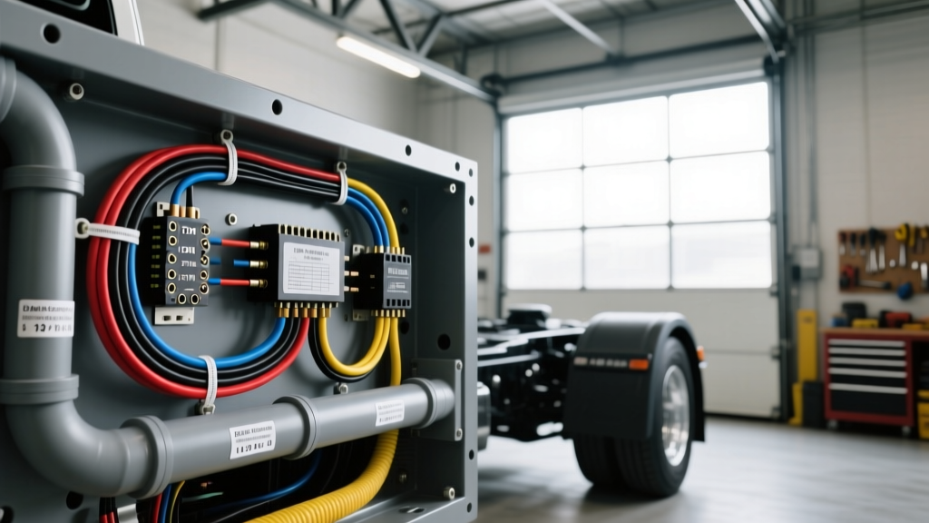
The Slate Auto Upfit PDM is typically located in the front trunk (frunk) or the dedicated under-bed utility enclosure. It serves as the centralized gateway for all LV accessory routing. Follow these steps to ensure a safe, OEM-compliant installation.
Step 1: Lockout/Tagout (LOTO) and Isolation
Never work on the LV system while the HV system is active. Engage the vehicle's service mode via the central diagnostic screen. Physically disconnect the 12V auxiliary battery negative terminal and remove the HV manual service disconnect (MSD) plug. Wait a minimum of 15 minutes for the DC-DC converter's internal capacitors to discharge. Verify zero voltage at the PDM using a CAT III multimeter.
Step 2: Selecting and Routing the Upfit Circuit
Identify the appropriate auxiliary circuit on the PDM based on your load requirements (see Pinout Reference below). When routing wires from the PDM to the rear bed or chassis, maintain a strict minimum clearance of 150mm (6 inches) from any HV orange cabling. This separation is mandated by ISO 6722-1 and SAE J1113 standards to prevent Electromagnetic Interference (EMI) from the HV inverter from corrupting your LV accessory signals or CAN bus data.
Step 3: Terminations and Connectors
Avoid using generic butt splices or electrical tape. Commercial EV upfits are subjected to severe vibration and thermal cycling. Use environmentally sealed connectors such as the Deutsch DT series or Molex MX150. For high-current ring terminals (e.g., M8 studs on the PDM busbar), use a calibrated crimp tool and torque the nut to the manufacturer's specification—typically 18 Nm (13 lb-ft) for an M8 terminal. Apply a layer of adhesive-lined dual-wall heat shrink over all crimps to prevent moisture ingress and galvanic corrosion.
Pinout Reference: Slate Auto Auxiliary PDM Connector
The primary upfit interface utilizes a sealed 12-pin Amp Superseal 1.5 connector. Below is the standard pinout for the commercial utility package. Always verify with the specific model year's service manual, as firmware updates can reassign programmable pins.
| Pin | Wire Color | Function | Max Rating | Notes |
|---|---|---|---|---|
| 1 | Red | 12V+ Constant (Battery) | 50A | Fused internally at 60A |
| 2 | Orange/White | 12V+ Ignition/Run | 20A | Active only when HV contactors are closed |
| 3 | Yellow | CAN-H (Upfit Telemetry) | 5A | Requires 120-ohm termination if end-of-line |
| 4 | Green | CAN-L (Upfit Telemetry) | 5A | Must be routed as twisted pair with Pin 3 |
| 5 | Black/White | Signal Ground | 10A | Clean ground for logic boards/sensors |
| 6 | Blue | PWM Output (Dimmer/Speed) | 2A | Programmable via fleet management software |
| 7 | Purple | Accessory Wake Signal | 1A | 12V logic signal to wake external inverters |
| 8 | Black | Power Ground | 50A | Must terminate to dedicated chassis stud |
Integrating High-Draw Accessories: Winches and Compressors
A common mistake when upfitting Slate Auto electric trucks is attempting to run high-inrush accessories, like a 12,000 lb winch or a heavy-duty PTO air compressor, directly off the PDM. A winch can draw upwards of 350A under peak load, which will instantly blow the PDM main fuse and potentially damage the DC-DC converter's internal MOSFETs.
The Solution: Secondary Buffer Battery Architecture
For loads exceeding 80A continuous or 200A peak, you must install a secondary, isolated 12V LiFePO4 buffer battery in the equipment bed. Use a heavy-duty battery isolator solenoid (such as the Victron Cyrix-Li) controlled by the PDM's 'Ignition/Run' circuit (Pin 2). When the truck is on, the DC-DC converter maintains the buffer battery. When the winch is engaged, the buffer battery absorbs the massive inrush current, shielding the truck's primary DC-DC converter. Ensure the buffer battery ground is tied to the truck's main chassis ground bus using a minimum of 2/0 AWG welding cable to prevent ground potential differences.
Common Wiring Mistakes and Troubleshooting Matrix
EV electrical systems are highly sensitive to voltage fluctuations and electromagnetic noise. Refer to this decision tree when diagnosing post-installation faults.
| Symptom | Probable Cause | Diagnostic & Fix |
|---|---|---|
| PDM throws CAN-bus U0100 code when auxiliary light bar is toggled. | Unshielded PWM wiring for the light bar driver radiating EMI into the CAN-H/CAN-L twisted pair. | Reroute CAN lines to maintain 150mm clearance. Install ferrite beads on the light bar power feed. Verify CAN bus termination resistance (should read 60 ohms across Pins 3 and 4). |
| DC-DC converter thermal throttling (Code P0A08) during winch operation. | Winch inrush current exceeds the 3.3kW DC-DC converter's peak limit, causing voltage sag below 11.5V. | Install a secondary 12V LiFePO4 buffer battery with an isolator solenoid to handle transient inrush loads. Upgrade winch feed to 2/0 AWG. |
| Telemetry module reboots randomly when HVAC compressor cycles. | Dirty power on the 12V Constant line due to shared grounding or lack of filtering. | Move telemetry power to a dedicated PDM circuit. Install an inline DC-DC isolated buck converter to provide clean, regulated 12V to the telemetry logic board. |
| Chassis ground stud shows signs of melting or discoloration. | Improper crimping or using a painted/unprepared chassis surface for high-current grounding. | Remove paint and primer down to bare metal. Apply dielectric grease after torquing the M8/M10 terminal to spec. Use a dedicated ground bus bar instead of daisy-chaining grounds. |
Final Safety and Compliance Notes
When upfitting Slate Auto electric trucks, always document your wiring modifications on the vehicle's upfit schematic diagram. Use National Truck Equipment Association (NTEA) guidelines for EV upfitting to ensure your modifications do not void the OEM HV battery warranty. Never pierce OEM wire insulation with 'scotch-lock' taps; always use proper splice connectors or PDM breakout harnesses. By respecting the DC-DC converter's limits and maintaining strict EMI separation, you can build a robust, reliable commercial EV platform that withstands the rigors of daily fleet operation.