Introduction to W-Series Electrical Architecture
The Chevrolet Astro and GMC Safari vans represent a unique era in General Motors' W-Series architecture. Produced from 1985 through 2005, these vehicles feature a complex, transitional electrical system that bridges the gap between simple analog circuits and early Class 2 Serial Data networks. When diagnosing severe electrical gremlins—ranging from parasitic battery draws to intermittent Passlock II immobilizer faults—technicians often look to the rigorous diagnostic methodologies championed by specialized regional shops. The benchmark standards frequently associated with high-level diagnostic centers, such as the specialized workflows documented by Astro Auto Electric Lomita technicians, emphasize a return to foundational circuit analysis over blind part swapping. This technical reference guide breaks down the core electrical specifications, wire routing architectures, and diagnostic protocols required to properly service the later-model (1996–2005) Astro van electrical system.
The Delco CS130D & CS144 Charging Architecture
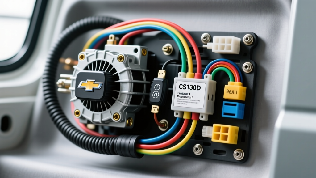
The heart of the Astro’s charging system relies on the Delco CS130D and, in higher-amperage applications, the CS144 alternator. Unlike older SI-series alternators, the CS (Charging System) series utilizes an internal voltage regulator controlled by a 4-pin connector. This connector is a frequent failure point due to heat degradation and terminal fretting corrosion. According to Delco Remy Alternator Specifications, the 4-pin pigtail serves distinct functions that must be verified with a digital multimeter (DMM) rather than a simple test light.
CS130D 4-Pin Regulator Connector Pinout
| Pin | Function | Wire Color | AWG Size | Diagnostic Voltage Spec |
|---|---|---|---|---|
| L | Lamp / PCM Wake-Up | Gray/Black | 18 AWG | 0V (Key Off) / 12V (Key On, Engine Off) |
| F | Field / PCM Duty Cycle | Gray | 18 AWG | PWM Signal (10% - 90% Duty Cycle) |
| P | Phase (Stator Reference) | N/A (Unused) | N/A | N/A (Often unpopulated in GM harnesses) |
| S | Voltage Sense | Red | 14 AWG | Must match Battery Positive (within 0.2V) |
Troubleshooting Insight: The 'S' (Sense) wire is critical. It must be connected directly to the battery positive or main fuse block via a 14 AWG red wire with an inline fusible link. If the Sense wire loses continuity or develops high resistance due to corrosion at the under-hood electrical center (UHEC), the internal regulator defaults to a fixed 13.8V output. This causes severe undercharging under heavy electrical loads, often misdiagnosed as a bad alternator.
Passlock II Anti-Theft Signal Tracing
The 1996–2005 Astro vans are equipped with the Passlock II anti-theft system. Unlike the older VATS system that relied on a resistor pellet embedded in the key, Passlock II utilizes a Hall-effect sensor integrated directly into the ignition lock cylinder. The system measures a specific voltage drop when the key is turned, sending a signal to the Body Control Module (BCM) and Powertrain Control Module (PCM) to enable the fuel injectors. Wiring harness chafing near the steering column shroud is a notorious failure mode. The Haynes GM Astro/Safari Repair Manuals provide baseline routing diagrams, but real-world diagnostics require precise voltage tracing.
Passlock II Ignition Cylinder Sensor Voltages
| Wire Color | Function | Key OFF | Key ON (Run) | Key CRANK |
|---|---|---|---|---|
| Yellow | 5V Reference (from BCM) | 0V | 5.0V | 5.0V |
| Black/White | Sensor Ground | 0V | < 0.05V | < 0.05V |
| Orange/Black | Signal Return (to BCM) | 0V | ~4.9V (No Magnet) | ~2.4V - 3.8V (Magnet Aligned) |
Real-World Failure Mode: If the Orange/Black signal wire develops a 2-ohm resistance due to chafing against the steering column tilt mechanism, the voltage drops below the PCM threshold during the crank cycle. This triggers a P1626 (Theft Deterrent Fuel Enable Signal Not Received) or P1631 code, instantly disabling the injectors and causing a crank-no-start condition. Always perform a voltage drop test on the signal wire while actively turning the lock cylinder.
Ground Distribution Network and Voltage Drop Testing
A comprehensive understanding of the Astro’s ground distribution network is non-negotiable for accurate diagnostics. GM utilizes a designated ground numbering system that clusters multiple circuits to single chassis tie-points. Over time, dissimilar metal corrosion and road salt infiltration increase resistance at these nodes, causing phantom voltage drops that mimic failed sensors or modules.
- G100 (Left Front Inner Fender): Located behind the battery tray. Handles the PCM, TCM, and main engine sensors (MAF, TPS, O2). Must be cleaned to bare metal and sealed with dielectric grease.
- G200 (Right Rear Quarter Panel): Handles the HVAC blower motor, rear lighting, and power window circuits. Prone to water intrusion from failing rear window seals.
- G300 (Engine Block Rear): The main engine block ground strap. If corroded, the starter motor will draw excessive amperage through the PCM ground paths, potentially frying the internal PCM driver circuits.
Testing Protocol: Voltage drop testing requires placing the multimeter positive lead on the component ground wire and the negative lead directly on the battery negative terminal while the circuit is under load. A reading greater than 0.1V DC indicates unacceptable resistance requiring terminal refurbishment.
Parasitic Draw Isolation Methodology
Diagnosing a dead-battery complaint on an Astro requires strict adherence to parasitic draw isolation protocols. The Astro’s Class 2 Data Link network can take up to 20 minutes to enter "sleep" mode after the ignition is turned off and the doors are closed. Interrupting the circuit before the modules sleep will yield false-high amperage readings. Following the circuit testing guidelines outlined by SAE International Automotive Standards, technicians must use a low-amp clamp or a multimeter with a dedicated milliamp shunt to measure draw without dropping the network voltage.
Step-by-Step Sleep Mode Verification
- Prepare the Vehicle: Close all doors, hood, and liftgate. Disable the under-hood lamp. Roll down the driver's window to reach the interior fuse block without opening the door.
- Connect the DMM: Set the DMM to the 10A scale. Connect in series between the negative battery terminal and the negative cable.
- Wait for Sleep: Wait a minimum of 20 minutes. You will hear the fuel pump relay click, followed by the BCM and PCM modules powering down. The draw should drop from ~2.5A to below 50mA (0.050A).
- Isolate the Fault: If the draw remains high, pull fuses one by one. If pulling the 'PCM/BCM' fuse drops the draw, use a breakout box to isolate the specific Class 2 Data Link module keeping the network awake (often a failing ABS module or digital radio).
Fuse Block Architecture and Maxi-Fuse Degradation
The under-hood electrical center (UHEC) and the interior instrument panel fuse block on the Astro are prone to terminal oxidation, particularly in the Maxi-fuse slots that supply the ABS module and HVAC blower motor. The 30A and 40A Maxi-fuses rely on a tight friction fit; when exposed to thermal cycling and moisture, the female terminals expand, creating high-resistance hotspots. This results in a voltage drop under load, causing the ABS module to throw low-voltage U-codes (e.g., U1000) or the blower motor to operate intermittently on high speed. Proper repair requires depinning the connector, cleaning with an electrical contact solvent, and applying a light coat of dielectric grease, rather than simply replacing the fuse and masking the underlying thermal damage.
Conclusion
Servicing the electrical system of the Chevrolet Astro requires patience, precise wiring schematics, and a refusal to guess. By adhering to the rigorous diagnostic standards—much like those championed by Astro Auto Electric Lomita specialists—technicians can accurately trace Class 2 data faults, repair degraded charging circuits, and eliminate parasitic draws, ensuring these legendary W-Series vans remain reliable on the road.