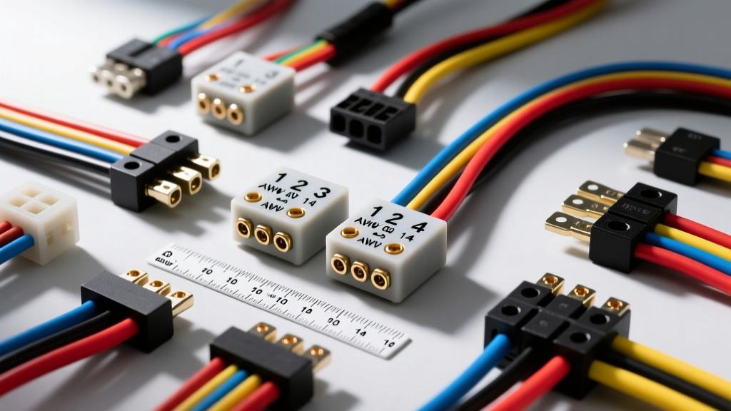
Introduction to KC Auto Electrical Architectures
Integrating high-output auxiliary lighting into modern vehicle electrical systems requires a dedicated, heavy-duty circuit architecture. OEM wiring harnesses are engineered for low-draw LED markers and signaling circuits, lacking the ampacity to support the transient inrush currents and sustained thermal loads of off-road halogen, HID, or high-lumen LED arrays. A properly engineered KC auto electrical harness bridges this gap by isolating the high-current load from the vehicle's delicate CAN-bus and BCM (Body Control Module) networks. By utilizing a direct-battery power feed, an electromechanical relay, and a low-current dashboard trigger, these systems ensure optimal voltage delivery to the lighting elements while protecting factory switches from thermal failure.
This technical specification reference details the exact wire gauges, insulation standards, relay pinout matrices, and grounding protocols required to install, diagnose, and validate KC auxiliary lighting electrical harnesses. Whether you are upgrading a Jeep Wrangler's fog light circuit or wiring a full roof rack array on a Ford Super Duty, adhering to these SAE and OEM-level specifications is critical for long-term electrical reliability.
Primary Cable Specifications & SAE J1128 Compliance
The backbone of any robust auto electrical harness is the primary cable. High-quality KC wiring kits utilize cross-linked polyethylene (XLPE) insulated wire, which offers superior resistance to heat, chemicals, and abrasion compared to standard PVC insulation. According to SAE J1128 standards for Low Tension Primary Cable, automotive wire must withstand continuous under-hood temperatures up to 125°C. The two most common variants used in these harnesses are GXL (General Cross-Linked) and TXL (Thin-wall Cross-Linked).
| AWG Size | Insulation Type | Max Ampacity (Free Air) | Nominal O.D. (inches) | Harness Application |
|---|---|---|---|---|
| 10 AWG | GXL / TXL | 40A - 55A | 0.131 - 0.145 | Battery to Relay (Pin 30), Relay to Load (Pin 87) |
| 12 AWG | GXL | 25A - 30A | 0.105 - 0.115 | Main Chassis Ground, Heavy Load Grounds |
| 16 AWG | TXL | 10A - 12A | 0.070 - 0.080 | Dashboard Switch Trigger, Relay Coil (Pins 85/86) |
| 18 AWG | TXL | 7A - 9A | 0.060 - 0.068 | Switch LED Indicator Illumination |
Note: Ampacity ratings assume a single conductor in free air at an ambient temperature of 25°C. Bundling multiple wires inside a split-loom conduit reduces heat dissipation and requires a 15-20% derating of the maximum current capacity.
4-Pin Mini ISO Relay Pinout & Wiring Matrix
The core switching component in a KC auto electrical kit is the 40A Mini ISO relay (often referred to as a Bosch-style relay). This electromechanical device uses a low-current electromagnetic coil to close a high-current contactor. Understanding the DIN 72552 terminal numbering system is mandatory for proper harness integration and troubleshooting.
| Pin Number | DIN Label | Standard Wire Color | Terminal Type | Function & Circuit Role |
|---|---|---|---|---|
| 30 | Common / Line | Red (10 AWG) | 6.3mm Blade | Direct battery power feed (post-fuse). Constant 12V-14.4V. |
| 87 | Normally Open (NO) | Red/White (10 AWG) | 6.3mm Blade | Switched power output to the auxiliary lighting load. |
| 86 | Coil Power | White/Blue (16 AWG) | 4.8mm Blade | Low-current trigger signal from the dashboard toggle switch. |
| 85 | Coil Ground | Black (16 AWG) | 4.8mm Blade | Ground path for the relay coil. Completes the trigger circuit. |
Relay Integration Best Practices
- Diode / Resistor Protection: When the relay coil is de-energized, the collapsing magnetic field generates a high-voltage inductive kickback (up to 100V). High-end KC auto electrical harnesses include an internal suppression resistor or flyback diode across pins 85 and 86 to protect sensitive BCM trigger circuits from voltage spikes.
- Terminal Crimping: Never use solder-only connections on relay spade terminals. Solder can wick up the wire strands, creating a rigid stress point that fractures under engine bay vibration. Always use a calibrated ratcheting crimp tool with nylon-insulated, heat-shrink female disconnect terminals.
Switch Integration & Dashboard Trigger Circuits
The dashboard toggle switch in a KC harness does not carry the load of the lights; it only carries the minimal current required to energize the relay coil (typically 150mA to 250mA). This allows the use of 16 AWG wire and prevents the dashboard switch from overheating.
Modern KC switch panels feature an integrated LED indicator that illuminates when the circuit is active. Wiring this LED requires careful attention to polarity and grounding:
- Power Source (Switch Input): Connect to an ignition-switched 12V source (e.g., a fuse box add-a-circuit on the wiper or radio circuit) to ensure the lights cannot be left on when the vehicle is off, preventing battery drain.
- Load Output (Switch Output): Routes to Relay Pin 86.
- LED Indicator Ground: The switch's internal LED requires a dedicated ground path. If the switch housing is plastic, a separate 18 AWG ground wire must be routed from the switch's negative terminal to a clean chassis ground.
Overcurrent Protection & Inrush Current Dynamics
Sizing the fuse correctly requires understanding the difference between steady-state draw and cold inrush current. A standard 100W H3 halogen off-road light draws approximately 8.3 Amps at a steady 14.4V system voltage (two lights = 16.6A). However, the cold filament resistance of a halogen bulb is roughly one-tenth of its hot resistance. Upon initial startup, the inrush current can spike to over 80 Amps for several milliseconds.
Therefore, a 30A ATO/ATC standard blade fuse is specified for a dual 100W halogen setup. The ATO fuse element is designed with a time-delay characteristic that tolerates brief inrush spikes without nuisance blowing, while still providing rapid thermal protection against sustained short circuits. For detailed time-current curves and automotive fuse specifications, refer to the Littelfuse ATO/ATC technical documentation. Always position the inline fuse holder within 6 inches of the battery positive terminal to ensure the entire length of the 10 AWG power feed is protected.
Grounding Protocols & Voltage Drop Limits
A failure in the ground circuit is the most common cause of auxiliary lighting dimness and relay chatter. Modern vehicle chassis are coated with E-coat (electro-deposition paint) and heavy undercoatings, which act as electrical insulators. Simply bolting a ring terminal to a painted frame rail will result in severe voltage drop and localized heating.
Proper Chassis Ground Execution:
- Surface Preparation: Use a wire wheel or sandpaper to remove paint, rust, and E-coat down to bare, shiny metal in a 1-inch diameter around the grounding point.
- Hardware Selection: Use an M6 or M8 zinc-plated flange bolt paired with an internal star lock washer. The star washer's aggressive teeth bite into the bare metal to maintain electrical continuity despite thermal expansion and vibration.
- Torque Specification: Torque M6 ground bolts to 8-10 Nm (71-88 lb-in) and M8 bolts to 20-25 Nm. Over-torquing can strip the captive weld nuts on unibody frames.
- Corrosion Prevention: After torquing, coat the entire ground terminal and bare metal area with dielectric grease or a dedicated battery terminal protector spray to prevent galvanic corrosion.
According to KC HiLiTES official installation guidelines and general automotive electrical standards, the maximum acceptable voltage drop across a high-current ground circuit (battery negative to light housing ground) should not exceed 0.10V to 0.20V under full load. Use a digital multimeter (DMM) set to DC Volts, placing the red probe on the battery negative post and the black probe on the light housing ground while the lights are active.
Troubleshooting Matrix: Common KC Harness Faults
| Symptom | Probable Root Cause | Diagnostic Action & Fix |
|---|---|---|
| Lights flicker or relay 'chatters' rapidly | High resistance on Pin 85 ground circuit or weak battery voltage causing coil dropout. | Measure voltage drop across Pin 85 to battery negative. Clean chassis ground and apply star washer. Check alternator output. |
| Lights are dim; full battery voltage not reaching bulbs | Undersized wire gauge, excessive wire length, or corroded inline fuse holder. | Perform voltage drop test from Pin 87 output to the light positive terminal. Replace corroded ATO fuse holders and verify 10 AWG continuity. |
| Dashboard switch LED is on, but lights do not activate | Blown main 30A ATO fuse, or failed contactor inside the relay (Pin 30 to 87). | Bypass the relay by jumping Pins 30 and 87 with a fused jumper wire. If lights turn on, replace the Mini ISO relay and inspect for moisture ingress. |
| Lights remain on after turning off the dashboard switch | Relay contacts welded together due to arcing, or trigger wire shorted to 12V. | Disconnect the trigger wire from Pin 86. If lights stay on, the internal relay contactor is fused; replace relay immediately. |
Conclusion
Building or repairing a KC auto electrical harness requires strict adherence to wire gauge specifications, proper relay pinout logic, and meticulous grounding techniques. By treating the auxiliary lighting circuit as a standalone, high-current subsystem isolated from the vehicle's sensitive CAN-bus networks, you ensure both the longevity of the lighting components and the safety of the vehicle's primary electrical architecture. Always validate your final installation with a digital multimeter to confirm voltage drop limits are within SAE specifications before finalizing wire routing and loom wrapping.