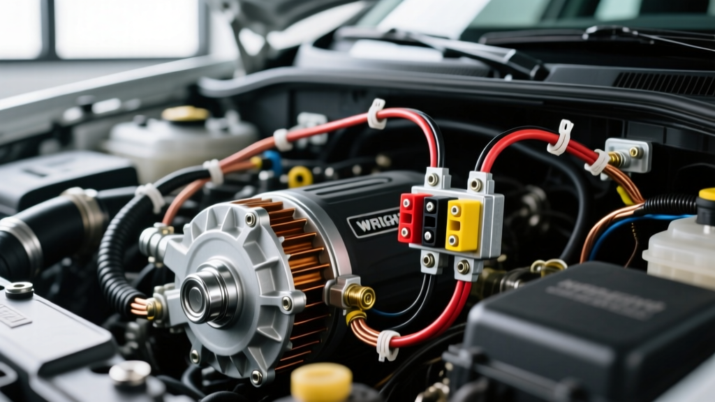
Introduction to the Wright Auto Electric High-Amp Upgrade
Upgrading the charging system in a classic muscle car, hot rod, or heavy-duty truck is a necessity when adding modern electrical loads like electronic fuel injection (EFI), high-draw electric cooling fans, and premium audio systems. The Wright Auto Electric high-output alternator kits are renowned in the restoration and custom automotive community for their robust internal voltage regulators, heavy-duty stator windings, and superior bearing life. However, simply bolting on a 140-amp or 200-amp alternator without upgrading the underlying wiring architecture is a recipe for melted harnesses, severe voltage drop, and catastrophic electrical fires. This practical how-to guide details the exact procedures, wire gauges, and torque specifications required to properly install a Wright Auto Electric high-amp alternator and integrate it into a 3-wire charging circuit using automotive-grade materials.
Pre-Installation Electrical System Audit
Before unbolting the factory alternator, you must establish a baseline for your vehicle's electrical health. A high-output alternator cannot compensate for poor grounding or corroded battery cables. Perform a voltage drop test on the existing positive battery cable and the engine-to-chassis ground straps. According to Auto Shop 101 Charging Systems diagnostics, a healthy power circuit should exhibit a voltage drop of less than 0.1V under load, while ground circuits should not exceed 0.2V. If your factory wiring shows higher resistance, clean all terminal mating surfaces with a wire brush and apply dielectric grease before proceeding. Additionally, verify that your battery has sufficient Cold Cranking Amps (CCA) and Reserve Capacity (RC) to buffer the high-amperage output; an aging lead-acid battery will struggle to absorb the ripple current generated by a high-output stator, leading to premature diode failure.
Required Tools and Wiring Materials
To execute a safe and reliable Wright Auto Electric alternator installation, abandon the cheap hardware store wire. You must use SAE-specification oxygen-free copper and proper crimping tools. Below is the mandatory bill of materials for a 140A to 200A system upgrade.
| Component | Specification | Application |
|---|---|---|
| Main Charge Wire | 4 AWG SAE J1127 Oxygen-Free Copper | Alternator BAT terminal to Starter Solenoid/Battery Positive |
| Sense Wire | 10 AWG TXL Cross-linked Polyethylene | Alternator Sense terminal to Battery Positive Post |
| Exciter Wire | 14 AWG TXL | Alternator Exciter terminal to 12V Switched Ignition Source |
| Overcurrent Protection | 8 AWG Fusible Link (120A rating) | Inline protection on the 4 AWG Main Charge Wire per SAE J1141 |
| Terminals | 3/8' Copper Ring Terminals (Hex Crimp) | Secure mating to BAT stud and solenoid stud |
| Heat Shrink | Dual-Wall Polyolefin with Adhesive Lining | Sealing crimps against moisture and corrosion |
| Fasteners | Grade 8 or Class 10.9 Metric/SAE Bolts | Alternator mounting brackets and pivot ears |
Step-by-Step Installation Procedure
Step 1: Battery Disconnect and Factory Harness Removal
Begin by disconnecting the negative battery terminal to isolate the chassis. Remove the factory alternator wiring harness. If your vehicle originally utilized a 1-wire internally regulated alternator or an older externally regulated setup, carefully tape off and secure the factory exciter and field wires to prevent them from shorting against the engine block. Unbolt the factory alternator from the mounting brackets. Inspect the pivot ears and adjustment brackets for elongation or fatigue; high-output alternators generate significant rotational torque, and worn brackets will cause belt slip and premature bearing wear.
Step 2: Mounting and Torque Specifications
Position the Wright Auto Electric alternator into the mounting brackets. It is critical to use the correct spacers and washers to ensure the pulley aligns perfectly with the crankshaft and water pump pulleys. Misalignment by even 2mm will destroy the serpentine or V-belt within hours of operation. Tighten the lower pivot ear bolt first. For standard 3/8'-16 SAE bolts, torque to 30-35 ft-lbs. For 10mm metric bolts, torque to 25-30 ft-lbs. Apply a single drop of blue medium-strength threadlocker (Loctite 243) to the adjustment bracket bolt to prevent vibration-induced loosening, then torque to 20 ft-lbs. Finally, install the high-grip serpentine belt or matched-set V-belts and tension according to the manufacturer's deflection specifications (typically 1/2 inch of deflection at the longest span under moderate thumb pressure).
Step 3: Routing the 4 AWG Main Charge Wire
The factory 10 AWG or 8 AWG charge wire is entirely inadequate for a high-amp alternator and will act as a resistor, choking off amperage and generating extreme heat. Cut a length of 4 AWG red SAE J1127 wire to route from the alternator BAT terminal to the main battery positive post or the starter solenoid main stud. Crucial Routing Rule: Maintain a minimum clearance of 3 inches from exhaust manifolds and headers. Secure the wire every 8 inches using UV-resistant nylon cable ties or aluminum P-clamps with rubber cushions. At the battery/solenoid end, install an 8 AWG fusible link rated for 120 amps. As outlined in the SAE J1141 Fusible Link standard, the fusible link must be four wire gauges smaller than the main cable it protects. This ensures the link will melt and sever the circuit in the event of a dead short before the 4 AWG wire can catch fire. Crimp all 3/8' ring terminals using a dedicated hex-crimp tool, and seal the barrels with dual-wall adhesive heat shrink.
Step 4: Exciter Wire and Sensing Circuit Configuration
While many high-amp alternators are sold as '1-wire' setups, relying on a single charge wire forces the internal regulator to sense voltage at the alternator output terminal, which is often inaccurate due to voltage drop across the engine bay. For optimal performance, wire the unit as a 3-wire system. Run a 10 AWG yellow sense wire from the alternator's 'S' (Sense) terminal directly to the positive battery post. Install a 10A inline ATO fuse within 6 inches of the battery connection to protect the sense circuit. Next, run a 14 AWG white exciter wire from the 'I' or 'EXC' terminal to a switched 12V ignition source. This wire provides the initial 'wake up' voltage to the internal voltage regulator, ensuring the alternator begins charging immediately upon engine start, even at low idle RPMs. For a comprehensive breakdown of bypassing factory idiot lights and wiring custom exciter circuits, reference the MAD Enterprises alternator wiring technical guides.
Wright Auto Electric Wiring Pinout and Color Code Chart
Use the following reference table to verify your terminal connections before applying power. Incorrect pinout wiring will instantly destroy the internal voltage regulator and rectifier diodes.
| Terminal Designation | Wire Color | AWG Size | Connection Destination | Function |
|---|---|---|---|---|
| BAT (Output Stud) | Red | 4 AWG | Battery Positive / Solenoid (via 120A Fusible Link) | Main DC output to charge battery and run vehicle loads. |
| S (Sense) | Yellow | 10 AWG | Battery Positive Post (via 10A Inline Fuse) | Reads true battery voltage to regulate output accurately. |
| I / EXC (Ignition) | White | 14 AWG | 12V Switched Ignition (Run/Start circuit) | Energizes the internal regulator field upon key-on. |
| F (Field - External Only) | Blue | 14 AWG | N/A (Leave disconnected on internally regulated units) | Used only if converting to an external vintage regulator. |
Post-Installation Testing and Troubleshooting
Once all connections are verified and tightened, reconnect the negative battery cable. Start the engine and allow it to idle. Using a digital multimeter (DMM), measure the voltage directly at the battery posts. You should immediately see a reading between 13.8V and 14.4V. Turn on all major electrical loads: headlights, high-speed electric cooling fans, blower motor, and rear defroster. The voltage should remain above 13.2V at idle. Rev the engine to 2,000 RPM; the voltage should stabilize around 14.2V. If the voltage drops below 12.8V under load at idle, your pulley ratio is likely incorrect, and the alternator is not spinning fast enough to reach its cut-in speed. If the voltage reads above 15.0V, immediately shut off the engine and check the yellow sense wire for a blown inline fuse or a broken connection; a lost sense circuit will cause the regulator to default to maximum output, boiling the battery acid and frying sensitive EFI computers.
Common Failure Modes
- Whining Noise from Audio System: Alternator whine indicates a poor engine-to-chassis ground or a failing diode trio. Verify your ground straps are clean, bare metal-to-metal connections.
- Melted BAT Terminal Boot: Caused by using undersized wire (e.g., 8 AWG instead of 4 AWG) or failing to use a hex-crimp tool, resulting in high resistance at the terminal.
- Belt Squeal on Startup: High-amp alternators require immense rotational force to magnetize the stator. Ensure your tensioner is functioning correctly and the pulley alignment is laser-straight.
By strictly adhering to these wire gauge requirements, torque specifications, and SAE safety standards, your Wright Auto Electric high-amp alternator installation will provide reliable, cool-running electrical power for even the most demanding automotive configurations.