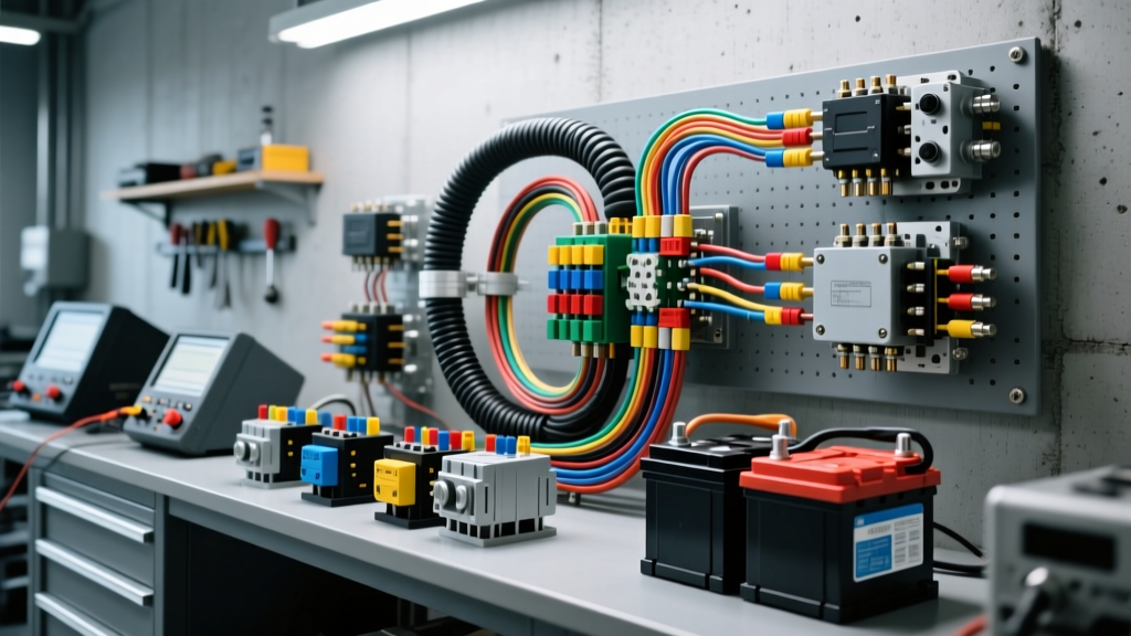
Benchmarking Commercial Standards: The Silva Truck & Auto Electric Inc Protocol
When engineering high-amperage electrical modifications for heavy-duty trucks, overland RVs, and commercial fleet vehicles, consumer-grade wiring practices inevitably lead to voltage drop, thermal runaway, and premature alternator failure. To achieve true reliability, professional installers look to commercial benchmarks. Shops like Silva Truck & Auto Electric Inc have long set the regional standard for heavy-duty electrical architecture, emphasizing robust cable management, precision crimping, and rigorous circuit protection. This guide translates those commercial-grade modification protocols into a comprehensive, actionable blueprint for your high-output alternator and dual-battery upgrade project.
System Architecture: High-Output Alternator & Dual Battery Setup
A standard factory 130A alternator cannot sustain the continuous parasitic loads of modern auxiliary systems (e.g., 12V compressor fridges, inverters, and high-draw winches). Upgrading to a 200A–250A heavy-duty alternator (such as a Leece-Neville or Denso HD series) requires a complete overhaul of the primary charge cables. The goal is to minimize resistance between the alternator B+ terminal and the battery banks, ensuring the voltage regulator receives accurate feedback.
Component Selection & AWG Specifications
According to SAE J1128 standards for low-tension primary cables, wire gauge selection must account for both continuous amperage and the physical length of the cable run to mitigate voltage drop. For heavy-duty applications, fine-strand copper welding cable is mandatory due to its superior flexibility and vibration resistance.
| Circuit Application | AWG Size | Strand Count | Insulation Type | Max Continuous Load |
|---|---|---|---|---|
| Alternator B+ to Starter/Battery | 1/0 AWG | 2109 (30 AWG strands) | EPDM / Neoprene | 250A |
| House Battery Positive Feed | 2/0 AWG | 2646 (30 AWG strands) | EPDM / Neoprene | 300A |
| Alternator Sense Wire | 10 AWG | Multi-strand THHN | PVC / Cross-linked | 30A (Fused) |
| Chassis Ground Straps | 2 AWG | Flat Braided Copper | Bare / Tinned | N/A (Ground path) |
Alternator Pinout & Regulator Sense Routing
One of the most critical failure points in high-output alternator upgrades is improper sense wire routing. If the internal or external voltage regulator measures voltage at the alternator B+ terminal rather than the battery post, the high amperage traveling through the 1/0 AWG cable will create a voltage drop. The regulator will falsely read low voltage and overcompensate, pushing 15.2V+ into the system and boiling the battery electrolyte.
Denso HD Alternator 3-Pin Connector Configuration
For popular Denso heavy-duty alternators used in commercial swaps, the 3-pin pigtail must be wired precisely to match OEM logic.
| Pin Number | Label | Wire Gauge | Color Code | Function & Routing |
|---|---|---|---|---|
| 1 | IG | 12 AWG | Red w/ White Stripe | Ignition switch 12V. Wakes the regulator. |
| 2 | L | 14 AWG | Green w/ Yellow Stripe | Dashboard warning lamp circuit. |
| 3 | S | 10 AWG | Red (Inline 30A Fuse) | Battery Sense. Must route directly to battery B+ post. |
Expert Insight: The 'S' (Sense) pin draws negligible current but requires a dedicated, fused 10 AWG wire routed cleanly alongside the main harness. Never splice the sense wire into a fuse block busbar; it must terminate directly at the positive battery terminal or the primary distribution stud to read true resting and charging voltage.
Execution: Crimping, Routing, and Torque Specifications
Commercial shops like Silva Truck & Auto Electric Inc reject solder-only connections for high-amperage DC circuits. Solder is brittle and prone to cracking under the high-frequency vibration of diesel engines and rough off-road terrain. The industry standard relies on mechanical cold-weld crimps.
Hydraulic Crimping & Heat Shrink Protocol
- Stripping: Use a calibrated wire stripper to remove exactly 7/8" of insulation from the 1/0 AWG cable. Do not nick the outer copper strands, which compromises the cross-sectional area.
- Crimp Selection: Use heavy-duty, tinned copper ring terminals (3/8" or 5/16" stud size depending on your B+ busbar). Ensure the terminal barrel matches the AWG exactly.
- Hydraulic Crimping: Use a 12-ton hydraulic crimper with a hexagonal die. Hex dies compress the fine-strand copper uniformly without cutting or crushing the outer strands, ensuring maximum surface contact and lowest millivolt resistance.
- Sealing: Apply 3:1 shrink ratio, adhesive-lined marine heat shrink over the terminal barrel. The internal thermoplastic adhesive must melt and extrude slightly from the edges, creating a watertight seal against battery acid vapor and road salt.
Hardware Torque Specifications
Loose terminals create micro-arcing and immense heat. Always use a calibrated inch-pound or Newton-meter torque wrench for electrical terminations.
- Alternator B+ Terminal (M8 Nut): 10-12 Nm (89-106 in-lbs). Over-torquing can strip the soft brass threads on the alternator rectifier bridge.
- Primary Distribution Busbar (M10 Stud): 15-20 Nm (132-177 in-lbs).
- Chassis Ground Bolt (M10 to Frame): 35-45 Nm. Must be secured to bare, unpainted steel using a hardened steel star washer to bite through the chassis coating.
Smart Isolator Integration & Circuit Protection
When adding a secondary AGM or Lithium house battery bank, a Voltage Sensitive Relay (VSR) or Automatic Charging Relay (ACR) is required to isolate the starting battery from auxiliary loads. Referencing the Blue Sea Systems Circuit Protection Guide, standard ANL fuses are often insufficient for large lithium banks due to their low Ampere Interrupting Capacity (AIC).
Fusing the Primary Charge Line
You must install a Class T Fuse (250A or 300A) within 7 inches of the battery positive terminal. Class T fuses offer an AIC of 20,000 Amps at 12V DC. If a dead short occurs across the 1/0 AWG cable, a lithium battery bank can discharge over 10,000A instantaneously. An ANL fuse (rated at only 2,700A AIC) may sustain an internal plasma arc and fail to clear the fault, resulting in a vehicle fire. Class T fuses safely shatter the ceramic element and extinguish the arc.
Real-World Failure Modes & Diagnostics
Even with premium components, improper execution leads to distinct electrical gremlins. Use a digital multimeter (DMM) and a load tester to diagnose these common upgrade failure modes:
1. Alternator Whine in Audio Systems
Symptom: High-pitched whining in the stereo or comms equipment that changes pitch with engine RPM. Cause: Ground loop or undersized alternator ground path. The alternator case is grounding through its mounting brackets, which may have corrosion or paint interference. Fix: Install a dedicated 2 AWG braided ground strap directly from the alternator casing ground lug to the engine block or chassis. Verify voltage drop across the new strap under load; it must read less than 0.10V DC.
2. VSR Rapid Clicking (Relay Chatter)
Symptom: The smart isolator solenoid rapidly clicks on and off when the engine is idling. Cause: Voltage drop in the sense wire or undersized charge cables. When the heavy auxiliary load kicks in, voltage at the starter battery drops below the VSR's disconnect threshold (usually 12.35V), dropping the load. Voltage immediately rebounds to 13.8V, reconnecting the relay, causing an infinite loop. Fix: Upgrade the VSR sense wire to 10 AWG and ensure the 1/0 AWG interconnect cables are free of high-resistance corrosion. Verify that the VSR's ground wire is tied to a clean chassis ground, not shared with high-draw inverters.
3. Premature Alternator Rectifier Burnout
Symptom: Alternator outputs 0V or erratic AC ripple voltage after a few months of use. Cause: Disconnecting the battery while the engine is running (load-dump testing) or running high-amperage inverters without a secondary battery buffer. The inverter's harmonic distortion and voltage spikes fry the alternator's diode trio. Fix: Never use the "pull the battery cable" test on modern HD alternators. Always ensure a healthy, high-capacity battery bank is connected to act as a capacitor and absorb transient voltage spikes, as outlined in TMC Recommended Practices for heavy-duty electrical systems.
Conclusion
Executing a heavy-duty electrical upgrade requires moving beyond basic consumer wiring kits. By adopting the rigorous methodologies championed by commercial experts like Silva Truck & Auto Electric Inc—focusing on SAE-compliant AWG sizing, hex-crimped terminations, Class T circuit protection, and dedicated sense routing—you guarantee a modification that withstands the brutal thermal and vibrational realities of heavy-duty automotive environments.