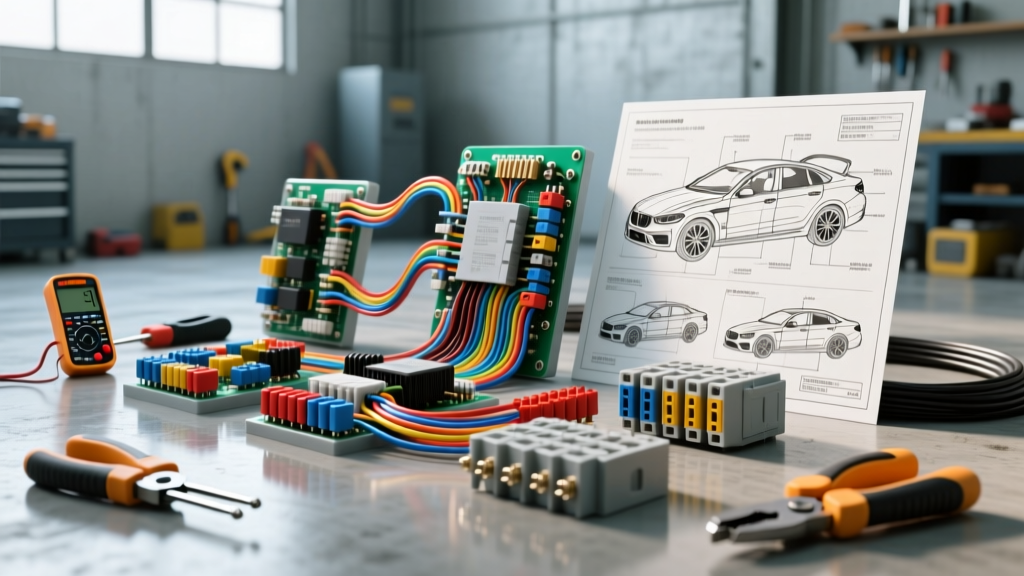
The Evolution of Advanced Auto Electric & Body Repair
Modern collision repair, custom fabrication, and restomod builds demand far more than basic 12-volt continuity testing. When building or upgrading an advanced auto electric & body shop, technicians must navigate complex multiplexed networks, high-current EV architectures, and strict OEM module programming requirements. Selecting the right diagnostic hardware, pass-thru interfaces, and weather-sealed connectors is critical to ensuring vehicle safety, network integrity, and long-term reliability.
This selection guide compares the industry-standard tools and components required for high-level automotive electrical and body integration, providing actionable specifications for wire gauges, pin configurations, and network topologies.
Diagnostic Hardware: Oscilloscopes vs. Advanced DMMs
The foundation of any advanced auto electric & body diagnostic bay is the ability to visualize network traffic and actuator waveforms. While Digital Multimeters (DMMs) are essential for basic voltage drop testing, they fall short when diagnosing micro-second glitches on CAN or LIN bus networks.
1. Automotive Oscilloscopes (e.g., PicoScope 4425A)
For deep network diagnostics, a 4-channel automotive oscilloscope is non-negotiable. The PicoScope 4425A features a sampling rate of 80 MS/s and 20 MHz bandwidth, allowing technicians to capture high-speed CAN FD (Flexible Data-rate) signals. When diagnosing a CAN bus fault post-collision, technicians should probe the CAN-H and CAN-L lines simultaneously. A healthy high-speed CAN network will show CAN-H resting at 2.5V and spiking to 3.5V, while CAN-L rests at 2.5V and drops to 1.5V. The differential voltage must remain clean, with the network terminated by two 120-ohm resistors (yielding 60 ohms across the bus when measured with a DMM).
2. Automotive Digital Multimeters (e.g., Fluke 88V)
The Fluke 88V remains the gold standard for heavy-duty and automotive DMMs, offering 1000V CAT III safety ratings and millisecond min/max recording. It is the preferred tool for verifying power and ground integrity at the Body Control Module (BCM) before attempting network diagnostics. For example, verifying that the BCM main power feed (typically a 10 AWG or 12 AWG red wire) experiences less than a 0.1V drop under a 20A load is a critical step before condemning a module.
Selection Verdict
- Choose an Oscilloscope for diagnosing communication network faults (CAN, LIN, FlexRay), injector waveforms, and sensor signal degradation.
- Choose an Advanced DMM for power/ground voltage drop testing, parasitic draw baseline measurements, and verifying termination resistance.
For comprehensive diagnostics, refer to the testing methodologies outlined by Pico Technology Automotive, which provides extensive guided tests for modern vehicle networks.
Module Reprogramming: J2534 Pass-Thru Interfaces
In modern auto body repair, replacing a damaged Body Control Module (BCM), lighting control module, or radar calibration module requires OEM software flashing. This is governed by the SAE J2534 Standard, which mandates a standardized API for pass-thru programming devices.
Comparing J2534 Interfaces
| Feature | DrewTech MongoosePro | Cardaq-Plus 3 |
|---|---|---|
| SAE Compliance | J2534-1 & J2534-2 | J2534-1 & J2534-2 |
| CAN FD Support | Yes (Hardware dependent) | Yes (Native) |
| DoIP Support | Yes (via Ethernet) | Yes (via Ethernet) |
| Best Application | Single-OEM specialized techs | Multi-OEM collision centers |
Technical Insight: When flashing a BCM after a front-end collision, ensure the vehicle battery is supported by a clean power supply maintaining exactly 13.5V to 14.2V. Voltage fluctuations during a CAN-based flash can corrupt the module's bootloader, bricking the BCM and requiring a costly replacement.
Connector & Wire Gauge Selection for Collision Repair
Body shops frequently need to repair or extend wiring harnesses routed through crumple zones, doors, and trunk lids. Using the correct weather-sealed connectors and wire gauges is vital to prevent corrosion and voltage drop. The TE Connectivity Automotive ecosystem and Deutsch series are the primary standards for harness repair.
Connector Specification Chart
| Connector Series | AWG Range | IP Rating | Crimp Tool Example | Primary Body Application |
|---|---|---|---|---|
| TE Superseal 1.5 | 14 to 20 AWG | IP67 / IP69K | TE 58499-1 | Headlamp pigtails, exterior sensors, ABS wheel speed |
| Deutsch DT | 14 to 18 AWG | IP68 | HDT-48-00 | Engine-to-body grounds, lighting modules, winch controls |
| Metri-Pack 280 | 10 to 18 AWG | IP67 | Delphi 12014213 | High-current BCM feeds, seat motor power, cooling fans |
Wiring Best Practices: When extending a CAN bus harness in a repaired quarter panel, always use 18 AWG or 20 AWG twisted pair wire. Maintain the factory twist rate (typically one twist every 1 to 1.5 inches) to preserve the common-mode noise rejection of the differential signal. Never untwist the CAN-H and CAN-L wires more than 50mm before the connector backshell.
Real-World Troubleshooting: Post-Collision LIN Bus Parasitic Draw
A common issue in advanced auto electric & body repair is a parasitic draw caused by a Local Interconnect Network (LIN) bus failing to enter sleep mode after a minor rear-end collision. The LIN bus is a single-wire, low-speed network (typically 19.2 kbps) used for non-critical body functions like ambient lighting, mirror dimming, and rain sensors.
Diagnostic Decision Tree
- Verify Sleep Mode Voltage: Connect an oscilloscope to the LIN wire (often purple/white or green/yellow depending on the OEM). When the vehicle is fully awake, the LIN bus pulses between 12V (recessive) and 1V-2V (dominant). When asleep, it should hold a steady 12V (battery voltage). If it holds at ~8V, a module is keeping the bus awake.
- Isolate the Faulty Node: The LIN bus operates in a master-slave topology. The master (usually the BCM) provides the 12V reference. If a slave node (e.g., a newly replaced ambient light sensor in the repaired roof console) has an internal short or incorrect pinout, it will pull the bus voltage down.
- Check Pinouts and Grounds: Disconnect the suspected slave module. Measure the resistance between the module's ground pin (Pin 3 on most 3-pin LIN connectors) and the vehicle chassis. It must read less than 0.5 ohms. If the ground is floating due to a missed body ground strap during reassembly, the module will back-feed the LIN bus, preventing the BCM from sleeping.
- Verify Ground Strap Torque: Body ground straps (typically M8 or M10 studs) must be torqued to OEM specifications (often 22-25 Nm for M8). The mating surface must be stripped to bare metal. Never apply dielectric grease to the mating surface of a high-current or network ground point, as it increases resistance and disrupts module logic.
Conclusion
Equipping an advanced auto electric & body facility requires moving beyond basic hand tools and embracing network-level diagnostics, OEM-compliant programming interfaces, and sealed connector systems. By investing in high-bandwidth oscilloscopes, adhering to SAE J2534 flashing protocols, and utilizing IP69K-rated connectors with precise crimp tooling, shops can ensure that every repaired vehicle meets factory electrical safety and communication standards.