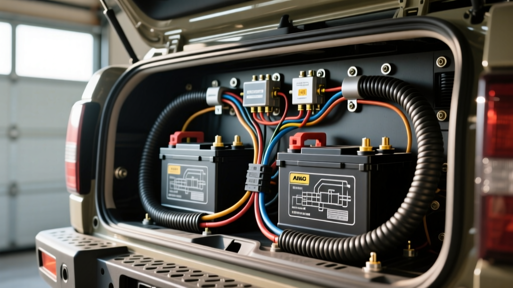
Architecting the Dual Battery Auto Electric Overhaul
Modern overland rigs and expedition vehicles demand far more than a standard OEM electrical layout can provide. Running 12V compressor fridges, high-lumen LED light bars, DC-DC chargers, and 12,000 lb winches simultaneously will quickly overwhelm a stock alternator and single-battery setup. When overhauling your vehicle's battery auto electric infrastructure, the primary objective is to isolate high-draw auxiliary loads from the starter battery, ensuring you always have enough cold cranking amps (CCA) to fire the engine after a weekend at base camp.
This guide details a comprehensive dual battery auto electric upgrade utilizing 1/0 AWG primary cabling, an automatic charging relay (ACR), and auxiliary AGM or LiFePO4 integration. We will cover SAE-compliant wiring practices, precise circuit protection calculations, and smart isolator pin configurations.
Core Components: Smart Isolators vs. VSRs
The heart of any dual battery auto electric system is the isolator. Older Voltage Sensitive Relays (VSRs) simply close a solenoid when they detect ~13.3V at the start battery and disconnect at ~12.7V. While cheap, VSRs suffer from contact arcing, high internal resistance, and voltage drop under heavy charging loads.
For a professional-grade modification, we recommend a Smart Isolator or a solid-state MOSFET-based Battery Management System (BMS) like the Redarc LBMS1225 or the Blue Sea Systems 7622 ML-ACR. The ML-ACR utilizes a latching relay that draws zero continuous current to maintain the closed state, eliminating the parasitic draw and heat generation inherent to traditional continuous-duty solenoids.
Battery Chemistry Matching
When linking a starting battery to a house battery, internal resistance and charge acceptance rates must be considered. Linking a flooded lead-acid starter battery directly to a Lithium Iron Phosphate (LiFePO4) house battery without a DC-DC charger will cause the lithium battery's extremely low internal resistance to pull unregulated, alternator-damaging current. For direct ACR linking, match a NorthStar Thin Plate Pure Lead (TPPL) AGM starter battery with a similar AGM auxiliary battery to ensure identical absorption voltage thresholds (typically 14.4V to 14.7V).
Wiring Architecture and AWG Specifications
Adhering to SAE J1128 standards for low-tension primary cable is critical for under-hood routing where ambient temperatures regularly exceed 125°C (257°F). Standard PVC-insulated wire will melt and short against the exhaust manifold. You must use cross-linked polyethylene (XLPE) or EPDM insulation, or route standard welding cable through high-temp split loom and fiberglass sleeving.
| Circuit Application | Wire Gauge (AWG) | Insulation Type | Overcurrent Protection | Terminal / Connector |
|---|---|---|---|---|
| Main Battery Link (Start to ACR) | 1/0 AWG | XLPE / EPDM | 250A ANL Fuse | 3/8" Heat-Shrink Ring |
| Main Battery Link (ACR to Aux) | 1/0 AWG | XLPE / EPDM | 250A ANL Fuse | 3/8" Heat-Shrink Ring |
| Chassis Ground Returns | 2 AWG | Flexible Welding | N/A (Ground) | 5/16" Ring to Frame |
| ACR Ignition Trigger Wire | 14 AWG | GXL / TXL | 5A ATO Blade Fuse | Deutsch DT / Spade |
| Aux Fuse Block Feed | 4 AWG | SGT / Welding | 150A Mega Fuse | M8 Ring Terminal |
Step-by-Step Installation Sequence
1. Main Power Routing and Crimping
Never use solder on high-current battery auto electric connections. Solder is brittle and will wick under the insulation, creating a stiff point that fractures under engine vibration. Instead, use a hydraulic hex-crimp tool to compress copper lugs onto your 1/0 AWG cable. A hex crimp provides a uniform, gas-tight cold weld that maintains superior conductivity. After crimping, seal the barrel with 3/8" dual-wall adhesive-lined heat shrink to prevent copper oxidation and electrolyte corrosion.
Route the 1/0 AWG positive cables along the factory wiring harness, securing them every 12 inches with UV-resistant zip ties. Maintain a minimum 3-inch clearance from exhaust headers. If crossing the chassis, use a heavy-duty rubber grommet to prevent the cable from chafing against sheet metal, which would cause a catastrophic dead-short.
2. Terminal Torque and Contact Resistance
Improper torque on battery studs is a leading cause of voltage drop and localized melting. For standard 3/8" (M10) battery terminal studs, apply exactly 10 to 12 ft-lbs (120-144 in-lbs) of torque using a calibrated inch-pound torque wrench. Coat the finished terminal with a dielectric grease or dedicated battery terminal protector spray to neutralize sulfuric acid off-gassing and prevent high-resistance corrosion buildup.
3. ML-ACR Control Circuit Pinout and Trigger Wiring
Smart isolators require a control signal to prevent the auxiliary battery from draining the starter battery when the ignition is off, even if surface charge voltages remain high. The Blue Sea 7622 ML-ACR utilizes a 4-pin control connector. Wire this circuit as follows:
- Pin 1 (Red 10 AWG): Connect to the Start Battery positive post via a 10A inline fuse. This powers the internal microcontroller.
- Pin 2 (Yellow 14 AWG): Ignition Trigger. Splice into a true ignition-switched 12V source (e.g., the wiper motor fuse tap or ignition relay coil). When this pin sees 12V, the ACR forces a combine state.
- Pin 3 (Black 10 AWG): Ground. Terminate to a clean, bare-metal chassis ground point within 18 inches of the isolator.
- Pin 4 (Green/White): Optional LED indicator or manual override toggle switch for winching operations.
Advanced Troubleshooting: Voltage Drop and Alternator Ripple
After completing the battery auto electric upgrade, you must validate the system under load. A common failure mode in dual-battery setups is the ACR rapidly clicking (chattering) between combined and isolated states. This is almost always caused by excessive voltage drop across undersized cables or dirty ground connections, which tricks the isolator into thinking the alternator has stopped charging.
Performing a Loaded Voltage Drop Test
With the engine running at 1,500 RPM and auxiliary loads drawing 40A, use a digital multimeter to measure the voltage directly at the alternator B+ terminal, and then at the auxiliary battery positive post. The difference should not exceed 0.2V. If you measure a 0.6V drop, your 1/0 AWG wire is either too long for the current draw, or you have a high-resistance crimp. Use the standard voltage drop formula:
V_D = (2 × K × I × L) / CM
Where K is the resistivity of copper (12.9 ohms per mil-foot at 75°C), I is current in amps, L is one-way length in feet, and CM is the circular mil area of 1/0 AWG (105,600 CM). If the math dictates a drop higher than 3% of system voltage (0.36V on a 12V system), you must upgrade to 2/0 AWG or 4/0 AWG cabling.
Checking Alternator Diode Ripple
Modern smart isolators and DC-DC chargers are highly sensitive to alternator noise. Switch your multimeter to AC Volts and probe the battery terminals while the engine is running. A healthy alternator should produce less than 50mV (0.050V) of AC ripple. If you measure 200mV or higher, one or more alternator rectifier diodes have failed. This AC ripple will cause MOSFET-based battery auto electric components to overheat and prematurely fail. Replace the alternator or install a high-capacitance noise filter on the sense wire before finalizing the project.