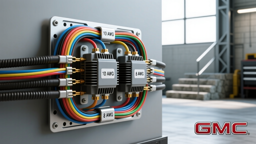
When discussing the Savannah auto electric ecosystem—frequently a colloquial search variation for the heavy-duty GMC Savana platform—technicians and upfitters face a unique set of electrical architecture challenges. The GMT-610 and newer GMT-610XX platforms are the backbone of commercial work vans, ambulance chassis, and overland camper conversions. Unlike standard passenger vehicles, the Savannah auto electric layout requires managing high-amperage auxiliary loads, dual-battery isolation, and OEM blunt-cut upfitter circuits. This advanced technical deep dive explores the precise wiring methodologies, AWG specifications, and relay logic required to safely expand the electrical capacity of these platforms without triggering CAN-bus faults or voltage drop failures.
High-Amp Alternator Upgrades and Output Routing
The stock alternator on a 4.8L or 6.0L V8 Savana typically produces between 105A and 145A. For work vans running hydraulic solenoids, inverters, or auxiliary HVAC, upgrading to a 220A+ unit (such as a Mechman or Powermaster high-output alternator) is mandatory. However, pushing 220+ amps through the factory 4 AWG or 2 AWG charge wire will result in catastrophic voltage drop and potential fire hazards due to thermal runaway.
According to SAE J1128 standards for low-tension primary cable, wire sizing must account for both continuous amperage and the physical length of the run. For a Savannah auto electric alternator upgrade, the charge wire must be routed from the alternator B+ terminal directly to the starter motor B+ stud or the primary positive battery post, bypassing the factory intermediate junction blocks.
Alternator Output Cable Sizing Chart
| Alternator Output | Wire Length (One Way) | Recommended AWG (Copper) | Fuse Rating (Mega-Fuse) |
|---|---|---|---|
| 145A (Stock) | < 5 ft | 2 AWG | 175A |
| 220A (High Output) | < 5 ft | 1/0 AWG | 250A |
| 220A (High Output) | 5 - 10 ft | 2/0 AWG | 250A |
| 320A (Extreme Duty) | < 5 ft | 2/0 AWG | 350A |
Always terminate 1/0 AWG and larger cables using closed-end copper lugs (e.g., Ancor or Klein) crimped with a hex-die hydraulic tool. Soldering large-gauge battery cables is discouraged in high-vibration automotive environments due to solder wicking and subsequent strand fatigue.
PWM Alternator Control and the L-Terminal Signal
Modern iterations of the Savannah auto electric platform utilize a LIN-bus or PWM-controlled voltage regulator internal to the alternator. The Body Control Module (BCM) sends a 5V pulse-width modulated signal to the alternator's 'L' (Logic) terminal to dictate the exact voltage setpoint. If an upfitter installs a high-output aftermarket alternator that relies on a simple 12V ignition-switched excitation wire, the BCM will detect an open circuit on the L-terminal. This triggers a 'Service Battery Charging System' DIC (Driver Information Center) message and may force the vehicle into a limp-home voltage mode, capping system voltage at 13.8V to protect sensitive ECU modules.
To bypass this without throwing U-codes, advanced auto electricians use an L-terminal simulator or retain the OEM voltage regulator harness while upgrading the stator and diode bridge. When measuring the L-terminal signal with an oscilloscope, a healthy BCM command will show a 5V square wave with a duty cycle varying between 10% (minimum charge) and 90% (bulk charge phase). Understanding this PWM logic is critical when diagnosing phantom battery drains or erratic voltmeter readings on the dash cluster.
Upfitter Blunt-Cut Circuits and Relay Integration
The true complexity of the Savannah auto electric system lies in the OEM upfitter provisions. GM provides a dedicated Body Builder Electrical Upfitter Guide (available via GM Fleet B2B), which details the location of blunt-cut wires intended for auxiliary lighting, PTO (Power Take-Off) controls, and beacon relays.
In the GMT-610 chassis, these wires are typically located under the driver’s seat or bundled near the left-hand B-pillar. Tapping into these circuits requires understanding the GM-specific color codes and the integrated Body Control Module (BCM) logic.
Common GM Savannah Upfitter Wire Color Codes
- Light Green/White Stripe: Auxiliary ignition-switched 12V+ (Fused at 15A via underhood bussed electrical center).
- Dark Blue: Left turn signal / hazard feed (often used for trailer sync relays).
- Brown/White Stripe: Park lamp feed (switched via headlamp switch PWM signal).
- Orange/Black Stripe: Battery positive feed (hot at all times, fused at 20A).
When integrating these low-current BCM outputs to drive high-draw accessories (like a 50A winch contactor or a 30A roof LED array), you must use a Bosch-style 5-pin relay. Connect the BCM blunt-cut wire to Pin 86 (Coil Positive) and Pin 85 (Coil Ground). The heavy accessory power is drawn directly from the distribution block through Pin 30, exiting via Pin 87 to the load. Never back-feed BCM logic circuits directly to a load, as the solid-state drivers inside the BCM will fail instantly under inductive kickback.
Auxiliary Battery Management and Isolation Topologies
For camper and work van conversions, managing a secondary house battery bank is a cornerstone of Savannah auto electric modifications. The factory electrical system utilizes a smart alternator (often controlled via the BCM regulating the L-terminal PWM signal). This means the alternator output voltage fluctuates between 12.8V and 15.0V depending on battery state-of-charge and ambient temperature.
Because of this variable voltage output, traditional solenoid-based battery isolators (which simply parallel the batteries when voltage exceeds 13.3V) are highly inefficient and can cause the BCM to throw a U-code (network communication fault) due to rapid voltage oscillations.
VSR vs. DC-DC Charger Architectures
Instead of a basic Voltage Sensitive Relay (VSR), advanced Savannah auto electric builds require a DC-DC charger (e.g., Redarc BCDC1225D or Victron Orion-Tr Smart).
- Input Wiring: Run 6 AWG wire from the starter battery positive to the DC-DC charger input, protected by a 40A ANL fuse within 18 inches of the terminal.
- Ignition Sense: Connect the charger's ignition sense wire to the Light Green/White upfitter blunt-cut wire. This ensures the charger only activates when the engine is running, preventing parasitic drain on the cranking battery.
- Output Wiring: Use 6 AWG wire to the auxiliary AGM or Lithium (LiFePO4) bank, sized according to the charger's maximum amperage (typically 25A or 40A).
Upgrading the Bussed Electrical Center (BEC)
The underhood Bussed Electrical Center (BEC) in the GMT-610 platform houses the primary high-current Mega-Fuses and high-amperage relays. When adding auxiliary loads that exceed the spare capacity of the BEC, installing a secondary marine-grade fuse block (such as a Blue Sea Systems ST-Series) is required. Mount the secondary fuse block on the inner fender well, ensuring at least 4 inches of clearance from the exhaust manifolds. Feed this block using 4 AWG primary wire tapped directly at the starter motor B+ stud, protected by a 150A Class-T fuse. This ensures that any catastrophic short in the upfitter wiring will isolate at the Class-T fuse without back-feeding through the OEM BEC and melting the factory harness.
Grounding Architecture and Star-Point Methodologies
A common failure mode in upfitted vans is poor grounding, leading to CAN-bus corruption and flickering lighting. The Savannah auto electric ground strategy relies on heavy-duty star-point grounds bolted to the chassis frame rails. When adding auxiliary grounds for inverters or high-amperage lighting, do not rely on sheet metal. You must drill through the frame rail, remove all paint and powder coating using a wire cup brush, and secure the ground lug using a Grade 8 flange bolt and a serrated flange nut torqued to 35 lb-ft. Apply a dielectric grease or fluid film over the completed connection to prevent galvanic corrosion. For inverters exceeding 1000W (drawing 80A+), the ground cable must be the exact same AWG and length as the positive 1/0 AWG supply cable to maintain impedance balance and ensure the Class-T fuse clears properly during a short-circuit event.
For further reference on commercial vehicle grounding standards, consult the NFPA 791 standard for commercial vehicle electrical systems, which outlines strict guidelines for chassis bonding and isolation in upfitted environments. By adhering to these precise AWG ratings, relay topologies, and OEM BCM logic parameters, technicians can safely expand the capabilities of the Savannah auto electric platform, ensuring reliable operation under the most demanding commercial and overland conditions.