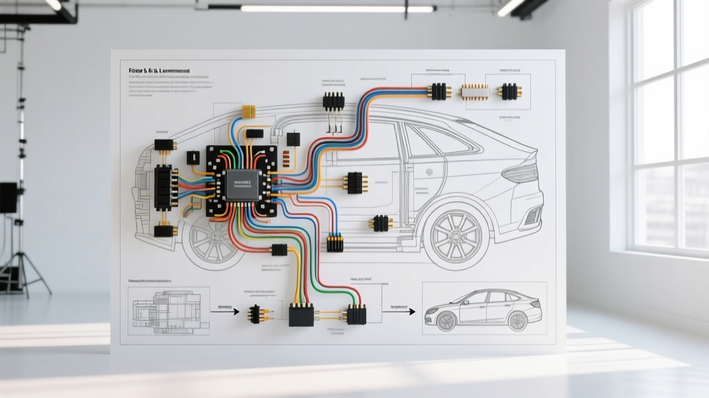
Introduction to the Floyd & Leonard Auto Electric Methodology
When diagnosing complex chassis wiring, intermittent CAN-bus faults, or heavy-duty starting circuit failures, guesswork is the enemy of efficiency. The Floyd & Leonard Auto Electric troubleshooting flow is a highly regarded, step-by-step diagnostic methodology utilized by master technicians to isolate electrical faults without resorting to the "parts cannon" approach. This framework prioritizes live-circuit voltage drop testing, precise parasitic draw isolation, and oscilloscope-backed alternator ripple analysis. By adhering to SAE standards and utilizing specific AWG (American Wire Gauge) thresholds, technicians can pinpoint failing connectors, corroded ground planes, and failing semiconductor bridges with surgical accuracy. Below is the comprehensive, step-by-step diagnostic flow adapted from the Floyd & Leonard Auto Electric protocols.
Phase 1: Parasitic Draw Isolation Flow
Modern vehicles feature complex multiplexed networks. A single module failing to enter "sleep mode" can drain a Group 48 AGM battery in 48 hours. The Floyd & Leonard Auto Electric methodology strictly forbids pulling fuses immediately, which can wake up dormant modules and invalidate test results.
Step 1.1: CAN-Bus Sleep Verification
Before measuring current, you must verify network sleep states. Connect a digital multimeter (DMM) to the OBD-II Data Link Connector (DLC). Pin 6 is CAN-High and Pin 14 is CAN-Low. With the ignition off and all doors closed, monitor the voltage. CAN-H should drop from 2.5V to 0.0V, and CAN-L should rise from 2.5V to 5.0V (or settle to 0.0V depending on the transceiver sleep state). If the network remains active (2.5V differential) after 45 minutes, a module is holding the network awake. According to AA1Car Battery Parasitic Drain Diagnostics, common culprits include aftermarket telematics devices, failing Bluetooth amplifiers, or a shorted CAN-H to 12V+ wire in the harness.
Step 1.2: The Inline Ammeter Matrix
Once sleep is confirmed, disconnect the negative battery terminal. Install a fused 10A jumper lead in parallel with your DMM set to the 10A scale. Reconnect the negative terminal through the jumper to prevent module reset. Wait an additional 15 minutes for the modules to re-enter sleep. If the draw exceeds 50mA (0.050A), begin the fuse-pull matrix. Note the exact milliamp drop when pulling specific fuses. A drop from 1.2A to 40mA when pulling the BCM (Body Control Module) fuse indicates an internal BCM short or a downstream load (like a glovebox LED switch or a shorted seat memory motor) keeping the BCM powered.
Phase 2: Starter & Ground Circuit Voltage Drop
A starter motor drawing 400 amps will expose any high-resistance fault in the primary feed or ground path. The Floyd & Leonard Auto Electric troubleshooting flow mandates voltage drop testing during cranking, never static resistance testing.
Step 2.1: Positive Feed Testing (AWG 4 to 2/0)
Set your DMM to DC Volts. Place the red probe directly on the battery positive post (not the clamp) and the black probe on the starter motor B+ terminal. Have an assistant crank the engine. For a standard 12V passenger vehicle utilizing 4 AWG or 2 AWG cross-linked polyethylene (XLPE) insulated cable per SAE J1128 Low Tension Primary Cable Standards, the maximum allowable voltage drop is 0.50V. For heavy-duty diesel applications using 2/0 AWG welding cable, the threshold drops to 0.30V. If your DMM reads 1.2V, the fault lies in the positive cable, the battery terminal clamp, or the intermediate junction block. Clean the SAE J563 tapered post and torque the clamp to exactly 12 Nm.
Step 2.2: Engine Block Ground Path
Place the red probe on the starter motor housing (bare metal) and the black probe on the battery negative post. Crank the engine. The maximum allowable drop on the ground side is 0.10V. If the drop is 0.45V, the engine-to-chassis ground strap (typically a braided 8 AWG or 6 AWG copper wire) is suffering from internal strand corrosion or fretting corrosion at the ring terminal. Always use a star washer and apply dielectric grease over the tightened connection to prevent galvanic corrosion between the copper terminal and aluminum engine block.
Phase 3: Alternator Diode Ripple Analysis
The alternator converts 3-phase AC voltage into DC voltage using a 6-diode bridge rectifier. If a single diode fails open, the alternator loses 33% of its output capacity, and the remaining AC ripple will destroy sensitive ECU capacitors and AGM battery plates.
Step 3.1: AC Millivolt Threshold Testing
Switch your DMM to AC Millivolts (mV). Connect the red lead to the alternator B+ output terminal and the black lead to the alternator aluminum case. Start the engine and elevate RPM to 2,000. Turn on the headlamps and blower motor to load the system. A healthy alternator will show an AC ripple of less than 50mV (0.050V AC). If the reading spikes to 250mV - 400mV AC, the diode trio is compromised. As detailed in Pico Auto Alternator Ripple Testing, an oscilloscope will reveal a flattened peak in the 3-phase waveform, confirming exactly which stator winding or diode pair has failed.
Floyd & Leonard Reference Specifications Table
| Circuit Type | Standard Wire Gauge (AWG) | Max Voltage Drop (Cranking/Load) | Common Connector Type | Torque Spec (Terminal) |
|---|---|---|---|---|
| Starter B+ Feed | 2/0 to 4 AWG | 0.50V (12V Sys) / 0.25V (24V Sys) | Ring Terminal (3/8" or 5/16") | 12 - 15 Nm |
| ECU Main Ground | 8 to 10 AWG | 0.10V | Metri-Pack 280 / Ring | 9 - 11 Nm |
| CAN-H / CAN-L Bus | 18 to 20 AWG | N/A (Check 60 Ohms Termination) | Deutsch DT04 / OBD-II DLC | N/A (Crimp verified) |
| Ignition Run Feed | 10 to 12 AWG | 0.30V | Weather-Pack / Fuse Tap | N/A |
| Alternator B+ Output | 8 to 4 AWG | 0.20V (at 80A Load) | Ring Terminal with Isolator | 10 - 12 Nm |
Common Failure Modes & Connector Pinouts
When executing the Floyd & Leonard Auto Electric troubleshooting flow, technicians frequently encounter specific, recurring failure modes related to environmental degradation and improper repair techniques.
- Metri-Pack 280 Fretting Corrosion: Common in engine bay sensors (e.g., MAF, CKP). The micro-vibrations of the engine wear away the tin plating on the male and female terminals, creating a high-resistance oxide layer. Fix: Do not simply spray contact cleaner. Replace the pigtail using a proper ratcheting crimp tool and seal the cavity with di-electric grease.
- Alternator Sense Wire Loss: Many modern alternators utilize a dedicated 18 AWG sense wire (often Red or Red/White stripe) connected directly to the battery positive or main fuse block. If this wire suffers a high-resistance fault, the alternator voltage regulator will overcompensate, pushing system voltage to 15.5V+ and boiling the battery electrolyte. Always voltage-drop test the sense wire with the engine running and loads applied.
- Starter Solenoid Trigger Circuit: The "S" terminal on the starter solenoid requires a minimum of 8.5V to engage the heavy-duty contactor. This circuit is typically fed via a 14 AWG or 16 AWG wire (often Purple or Yellow with a Red tracer) routed through the ignition switch, park/neutral safety switch, and starter relay. If the engine clicks but won't crank, back-probe the "S" terminal during a crank attempt. A reading below 8.0V indicates a failing ignition switch or corroded neutral safety switch pins.
By strictly following this step-by-step diagnostic flow, you eliminate assumptions, rely on empirical electrical data, and ensure that every repair meets the rigorous standards expected of top-tier auto electrical specialists.