The Critical Role of Precision in Auto Electric Repair
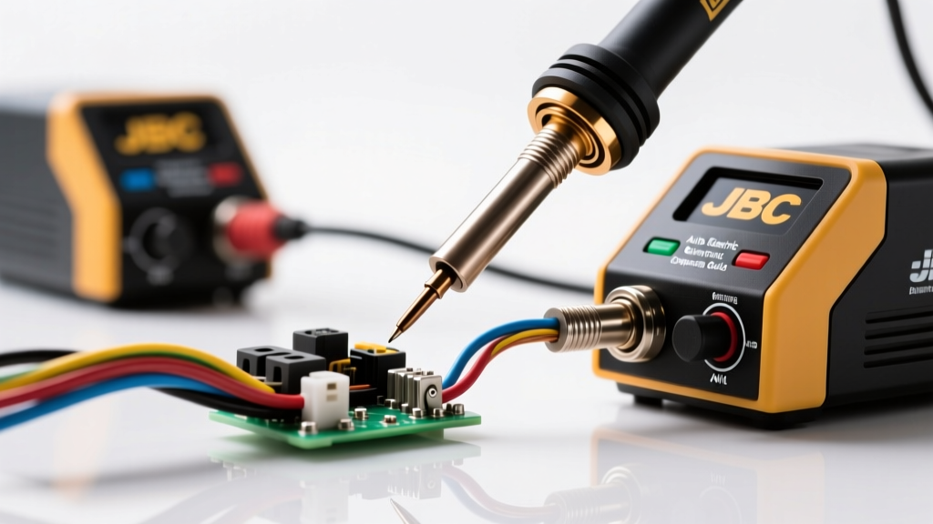
Automotive electrical diagnostics frequently culminate in physical wiring repairs. Whether you are rebuilding a melted GM alternator pigtail, repinning a Bosch ECU connector, or splicing a high-current starter cable, the thermal profile of your soldering equipment dictates the longevity of the repair. Standard hardware store soldering irons lack the thermal recovery required for heavy-gauge automotive wire, while oversized guns risk melting delicate sensor jackets. This is why the jbc auto electric workstation ecosystem has become the gold standard for professional automotive electricians and master technicians.
Unlike traditional ceramic heating elements, JBC’s exclusive cartridge system integrates the heater directly into the tip. This architecture delivers instantaneous heat transfer and rapid thermal recovery, which is essential when working with wires that act as massive heat sinks. In this comprehensive product comparison and selection guide, we will break down the best JBC setups for automotive applications, map specific tips to standard AWG sizes, and outline SAE-compliant harness repair protocols.
JBC Station Comparison for Automotive Applications
Selecting the right base station depends on the specific electrical systems you service. Below is a technical comparison of the most relevant JBC systems for auto electric work, benchmarked against a standard industry alternative.
| Feature | JBC CD-2BQE (General Auto) | JBC T245-0 (Precision/ECU) | Weller WE1010 (Budget Alt) |
|---|---|---|---|
| Max Power Output | 130W (Instantaneous) | 65W (Instantaneous) | 70W (Peak) |
| Heat-Up Time | < 2 Seconds | < 2 Seconds | ~45 Seconds |
| Handpiece Weight | 10.5g (Excluding cord) | 9g (Excluding cord) | 45g (Standard) |
| Tip Compatibility | C245 Cartridge Series | T245 / C245 Series | ETA / ET Series |
| Best Auto Application | Sensors, Lighting, 12-18 AWG | ECU Repinning, CAN Bus, 22+ AWG | Basic tail light repairs |
For a dedicated jbc auto electric setup, the JBC CD-2BQE is the undisputed workhorse. Its 130W output allows it to handle 14 AWG to 10 AWG wires (common in fuel pump modules and ABS harnesses) without the temperature dropping below the solder's liquidus state. For delicate airbag clock-spring repairs or CAN bus splicing where 22 AWG to 24 AWG wires are used, the JBC T245-0 offers unparalleled micro-precision.
Matching JBC Tips to Automotive AWG & Terminals
The most common mistake in automotive soldering is using a tip with insufficient thermal mass for the wire gauge. Automotive primary wire (specified under SAE J1128) features thick PVC or XLPE insulation that requires careful heat management to avoid jacket burn-through.
1. Fine Gauge (22 AWG - 24 AWG): CAN Bus, Airbags, ECU Pins
- Target Wires: High-speed CAN (CAN-H/CAN-L), SRS airbag squib circuits, Delphi/Molex micro-timer terminals.
- Recommended JBC Tip: C245-001 (Conical 0.1mm) or C245-105 (Bent Conical).
- Temperature Setting: 320°C (608°F).
- Technique: Use a minimal amount of 0.5mm diameter Sn63/Pb37 rosin-core solder. The fine tip prevents accidental bridging of adjacent ECU pins spaced at 2.54mm.
2. Medium Gauge (14 AWG - 18 AWG): Sensors, Injectors, Lighting
- Target Wires: Wideband O2 sensors (Bosch LSU 4.9), fuel injector pigtails, GM Weather-Pack circuits.
- Recommended JBC Tip: C245-945 (Chisel 1.8mm x 5mm) or C245-724 (Miniature Spoon).
- Temperature Setting: 350°C (662°F).
- Technique: The spoon tip is exceptional for 'drag soldering' or cup-style terminals found in Deutsch DT connectors, allowing the solder to pool evenly inside the terminal cup before inserting the stripped wire.
3. Heavy Gauge (8 AWG - 10 AWG): Alternators, Starters, High-Current
- Target Wires: Alternator sense/charge wires, starter solenoid triggers, high-amperage cooling fan relays.
- Recommended JBC Tip: C470-111 (Heavy Chisel 4mm) paired with the larger T470 handpiece, or a heavy-duty C245-116 if using the standard handpiece.
- Temperature Setting: 380°C (716°F).
- Technique: Pre-tin both the male and female strands separately before joining. The 8 AWG copper strands will rapidly wick heat away from the joint; the high thermal mass of the C470 tip prevents cold solder joints.
Real-World Scenario: GM CS130/CS144 Alternator Pigtail Repair
A classic auto electric failure is the melted 4-pin connector on GM CS-series alternators. The standard repair requires splicing a new pigtail into the existing engine harness. The pinout typically includes:
- Terminal S (Sense): Red or Brown, 12 AWG. Carries full battery voltage to the internal regulator.
- Terminal L (Lamp): Brown/White, 18 AWG. Connects to the dashboard charge indicator.
- Terminal F (Field): Gray, 18 AWG. PWM signal to the PCM for load management.
- Terminal P (Phase): Black, 18 AWG. Tachometer signal reference.
Because the 12 AWG Sense wire requires significantly more heat than the 18 AWG control wires, a standard iron forces the technician to either burn the 18 AWG insulation or fail to properly flow the solder on the 12 AWG wire. Using a JBC station, the technician can swap from a C245-945 (for the 12 AWG) to a C245-724 (for the 18 AWG) in less than three seconds, ensuring every splice meets IPC-A-620 standards for wetting and fillet formation.
Troubleshooting Cold Solder Joints in 12V Systems
Even with premium equipment, automotive environments present unique challenges. If you are experiencing intermittent voltage drops or high-resistance faults after soldering, evaluate the following failure modes:
- The Heat Sink Effect: When soldering near a brass or copper bulkhead connector, the terminal absorbs heat faster than a standard iron can provide it. The solder forms a dull, grainy 'cold' joint. Fix: Increase JBC temperature by 20°C and use a wider chisel tip to maximize surface contact area.
- Strand Oxidation: Automotive harnesses exposed to under-hood heat cycles develop heavy oxidation. Standard rosin flux cannot penetrate this. Fix: Apply a no-clean liquid flux (e.g., Kester 951) to the bare strands before applying heat. Never use acid-core plumbing solder, as the residual acid will corrode the copper strands and cause an open circuit within months.
- Vibration-Induced Fractures: Solder is brittle. A rigid solder joint on a flexible engine harness will crack under engine vibration. Fix: Always use a staggered splice technique and encapsulate the joint in dual-wall, adhesive-lined polyolefin heat shrink (3:1 shrink ratio). The melted polyamide inner liner provides the necessary strain relief.
Material Science: Selecting Solder for Automotive Harnesses
While the consumer electronics industry has largely transitioned to lead-free SAC305 (Tin/Silver/Copper) solders to comply with RoHS directives, the automotive aftermarket and motorsport sectors heavily favor traditional Sn63/Pb37 (63% Tin / 37% Lead) eutectic solder.
Sn63/Pb37 has a distinct liquidus and solidus point of 183°C (361°F), meaning it transitions from solid to liquid instantly. This eliminates the 'plastic' or 'pasty' state found in non-eutectic alloys, which is critical when working inside tight engine bays where maintaining perfect stillness during the cooling phase is nearly impossible. Furthermore, the addition of lead significantly reduces the formation of 'tin whiskers'—microscopic crystalline structures that can bridge adjacent pins in tightly packed ECU connectors, causing catastrophic short circuits in low-voltage logic circuits.
Final Verdict for the Auto Electrician
Investing in a jbc auto electric soldering ecosystem is not merely about purchasing a tool; it is about adopting a methodology that prioritizes joint integrity and harness longevity. The JBC CD-2BQE, paired with a curated selection of C245 cartridge tips, bridges the gap between micro-electronics precision and heavy-gauge power cable repair. By matching the correct tip geometry to the specific AWG and adhering to SAE and IPC harness repair standards, technicians can eliminate comebacks, prevent parasitic draws caused by corroded splices, and ensure the vehicle's electrical architecture operates flawlessly for years to come.