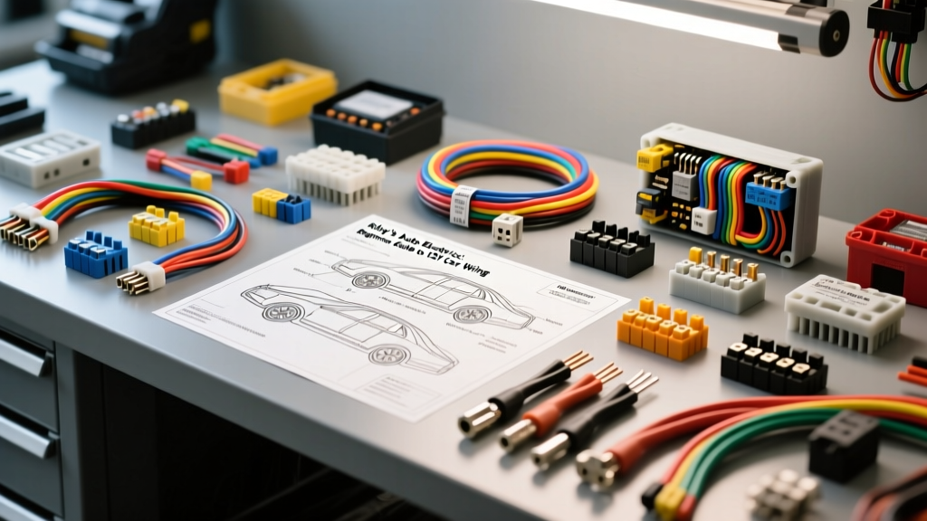
The Core Philosophy of Riley's Auto Electrics
When veteran master technicians discuss foundational automotive diagnostics, they often refer to the principles championed by classic, old-school shops. The 'Riley's Auto Electrics' methodology represents a back-to-basics approach to 12-volt DC vehicle systems. Instead of relying exclusively on expensive bi-directional scan tools, this philosophy teaches beginners to understand the raw physics of electricity: voltage, current, resistance, and the critical importance of the return path. Whether you are repairing a dim headlight on a 1998 Honda Civic or installing an aftermarket air conditioning compressor clutch on a classic Ford truck, mastering these fundamentals is non-negotiable.
In this comprehensive beginner's guide, we will break down the essential concepts of automotive wiring, from understanding American Wire Gauge (AWG) specifications to decoding standard ISO relay pinouts and performing precise voltage drop tests.
Essential Tools for the Beginner Auto Electrician
Before cutting a single wire, you must equip yourself with the correct diagnostic instruments. The most dangerous tool in a beginner's arsenal is the standard incandescent test light. While useful for verifying heavy battery power, a test light draws between 250mA and 500mA of current. If you accidentally probe a modern Controller Area Network (CAN-bus) line or an airbag squib circuit with a test light, you can instantly fry a $1,500 control module or deploy an SRS airbag.
- Digital Multimeter (DMM): A high-impedance DMM (minimum 10 Megohms) is mandatory. It draws virtually zero current, allowing you to safely measure reference voltage (5V) from Engine Control Units (ECUs) and sensor grounds.
- Power Probe or Fused Jumper Wires: For actuating components safely without risking a dead short.
- Wire Strippers and Crimpers: Avoid cheap combination pliers. Use dedicated ratcheting crimpers to ensure a gas-tight connection between the copper strands and the terminal barrel.
Understanding AWG Wire Sizing and Color Codes
Automotive wire is distinctly different from standard household solid-core wire. According to SAE International J1128 standards, automotive primary cable must be highly stranded (often 19 to 41 individual copper strands per gauge) to withstand the constant high-frequency vibration of a running internal combustion engine. Using solid-core wire in a vehicle will result in work-hardening, micro-fractures, and eventual open circuits.
Below is the standard reference chart for selecting the correct wire gauge based on continuous amperage loads in a 12V DC system. Note that as wire length increases, voltage drop increases, requiring you to step up to a thicker wire gauge for runs exceeding 10 feet.
| AWG Size | Cross-Section (mm²) | Max Continuous Amps | Standard Insulation Color | Common Automotive Application |
|---|---|---|---|---|
| 18 AWG | 0.75 mm² | 5A - 7A | White / Light Blue | ECU sensor signals, dash illumination, CAN-bus lines |
| 14 AWG | 1.50 mm² | 15A | Green / Orange | Tail lights, horn circuits, interior dome lights |
| 12 AWG | 2.50 mm² | 20A | Yellow / Red | Fuel pump power, 12V cigarette lighter sockets, power seats |
| 10 AWG | 4.00 mm² | 30A | Blue | High-amp lighting harnesses, power window motors, ABS pumps |
| 8 AWG | 8.00 mm² | 50A | Black / Red | Starter solenoid feeds, high-output alternator B+ outputs |
The 4-Pin Relay: The Heartbeat of Auto Electrics
Relays allow a low-current switch (like a dashboard headlight toggle drawing 0.5A) to control a high-current load (like a pair of 55W halogen fog lights drawing 9A) without melting the switch contacts. The standard Bosch-style ISO mini relay is the most ubiquitous component in automotive wiring.
According to the Hella Tech World Relay Guide, understanding the DIN standard pin numbering is critical for troubleshooting and installing aftermarket accessories like electric AC compressors or off-road light bars.
ISO Mini Relay Pinout Configuration
- Pin 85 (Coil Ground): Connects to the vehicle chassis ground or a dedicated ECU ground driver.
- Pin 86 (Coil Power): Receives switched +12V from the dashboard toggle switch or ignition relay.
- Pin 30 (Common / B+): Direct battery power, always protected by an inline fuse or fuse box tap.
- Pin 87 (Normally Open - NO): The output that sends +12V to the high-amp load (e.g., the AC compressor clutch coil) only when the relay coil is energized.
Pro-Tip: When wiring inductive loads like compressor clutches or fuel pumps, always wire a reverse-biased flyback diode across pins 85 and 86 (cathode to 86, anode to 85). This suppresses the high-voltage inductive spike generated when the relay coil collapses, protecting sensitive solid-state switching transistors inside modern vehicle BCMs (Body Control Modules).
Voltage Drop Testing: The Ultimate Diagnostic Secret
The most common mistake beginners make is testing for 'continuity' or measuring resistance on a live circuit, which can blow the internal fuse of a multimeter. Furthermore, a wire with only one intact copper strand will show 0.0 ohms of continuity on a multimeter, but it will completely fail to carry the 15 amps required to run a fuel pump under load.
The Riley's Auto Electrics method relies heavily on Voltage Drop Testing. As explained in the Fluke Automotive Voltage Drop Guide, voltage drop measures the exact amount of electrical 'pressure' (voltage) consumed by unwanted resistance in a circuit while it is under load.
Step-by-Step Voltage Drop Diagnosis
- Energize the Circuit: Turn on the failing component (e.g., a slow-moving power window motor or a dim headlight).
- Set DMM to DC Volts: Place your multimeter in the 20V DC range.
- Test the Power Side: Place the red probe on the battery positive terminal and the black probe on the power input pin at the component. A reading above 0.2V indicates excessive resistance (corrosion, loose crimp, or undersized wire) on the power feed.
- Test the Ground Side: Place the red probe on the metal casing of the component (or the ground wire pin) and the black probe on the battery negative terminal. A reading above 0.1V indicates a bad ground.
Acceptable Limits: SAE standards dictate a maximum voltage drop of 0.1V per connection or splice, and no more than 0.5V total drop for an entire high-current circuit. For sensitive 5V ECU sensor reference circuits, the maximum allowable drop is a mere 0.05V.
Common Grounding Mistakes (and How to Fix Them)
Electricity does not just flow 'to ground'; it must complete a continuous, low-resistance loop back to the negative terminal of the alternator and battery. The chassis is simply a massive, imperfect copper wire. Over 40% of all automotive electrical gremlins—ranging from flickering dashboards to erratic fuel injector pulse widths—are caused by degraded ground points.
The Anatomy of a Perfect Chassis Ground
When repairing or adding a new ground circuit (such as for an aftermarket audio amplifier or a relocated ECU), follow these strict fabrication rules:
- Bare Metal Contact: Never ground to painted steel, powder-coated brackets, or rusted surfaces. Use a wire wheel or 80-grit sandpaper to expose bright, bare metal.
- Proper Terminals: Use closed-loop (ring) terminals, never open-fork (spade) terminals, for chassis grounds. Vibration will eventually cause a spade terminal to slip off the stud, creating an open circuit or an arc fire.
- Adhesive-Lined Heat Shrink: Always use adhesive-lined polyolefin heat shrink over the crimp barrel. When heated, the inner glue melts and seals out moisture and road salt, preventing galvanic corrosion from wicking up into the copper strands.
- Star Washers and Dielectric Grease: Place a steel star washer between the ring terminal and the bare metal chassis to bite through any microscopic oxidation. Once bolted down and torqued to spec, coat the entire terminal in dielectric grease to seal out oxygen and moisture.
Decoding DIN vs. SAE Wiring Diagrams
To truly master auto electrics, you must be able to read factory service manuals. European vehicles (BMW, VW, Audi) typically use DIN-standard wiring diagrams, which trace the physical routing of the wire harness and show exact connector cavity numbers (e.g., Connector X254, Pin 14). American and Asian vehicles often use SAE-style block diagrams, which prioritize logical circuit flow over physical routing, showing the power source, switch, relay, and load in a linear, top-to-bottom format.
When troubleshooting a complex fault like a parasitic battery draw, cross-referencing both diagram styles allows you to understand not only how the circuit functions logically, but also where the physical splice pack (e.g., GM's famous SP101 or SP205 harness tape-wrapped splices) is located behind the dashboard kick panel.
Conclusion: Patience and Precision
The Riley's Auto Electrics approach is not about taking shortcuts; it is about understanding the invisible forces moving through your vehicle's copper veins. By respecting AWG sizing limits, mastering the ISO relay, utilizing voltage drop tests instead of guesswork, and fabricating flawless ground connections, you elevate yourself from a parts-changer to a true automotive electrical diagnostician. Keep your multimeter calibrated, your crimpers sharp, and always verify the return path.