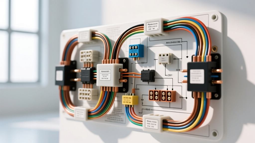
Introduction to PH Auto Electrical Environments and Architecture
When diagnosing PH auto electrical systems, technicians must account for two distinct but overlapping definitions of "PH." First, it refers to the Philippine market environment, characterized by extreme ambient heat (often exceeding 38°C in traffic), high humidity, and exposure to corrosive salt air. Second, in modern ASEAN-spec vehicle wiring diagrams (such as the Toyota Vios NCP150 or Innova AN40), "PH" designates the Power Hold relay circuit, which maintains ECU voltage post-ignition for data logging and thermal management. Understanding both the environmental stressors and the specific Power Hold architecture is critical for accurate, step-by-step troubleshooting.
Vehicles operating in these conditions suffer from accelerated PVC insulation degradation, terminal fretting corrosion, and voltage drop issues that standard diagnostic trees often miss. This guide provides a comprehensive, step-by-step troubleshooting flow tailored to these specific electrical architectures, utilizing precise AWG ratings, pin configurations, and OEM torque specifications.
Phase 1: Power Hold (PH) Relay and Main EFI Circuit Flow
The Power Hold (PH) circuit is designed to keep the Engine Control Module (ECM) energized for 10 to 30 seconds after the ignition is turned off. This allows the ECU to log post-shutdown data, run auxiliary cooling fans, and reset adaptive memory tables. In high-heat environments, the PH relay contacts often pit or carbonize, leading to parasitic draws or failure to log critical DTCs.
Step-by-Step PH Relay Diagnostic Flow
- Locate the EFI Main / PH Relay: Typically found in the engine compartment relay block. Identify the 4-pin or 5-pin configuration (Standard ISO mini relay).
- Verify Coil Resistance: Remove the relay. Measure resistance between Pin 85 (Coil Ground) and Pin 86 (Coil + / IG). Specification should be 65–85 ohms at 20°C. If reading is >100 ohms, the internal coil is degraded by heat.
- Test Switched Power Feed: With the relay removed and ignition ON, probe Pin 86 in the harness connector. You must read battery voltage (12.2V - 12.6V). A reading below 11.5V indicates a voltage drop in the Black/Orange (IG) wire tracing back to the ignition switch.
- Verify Power Hold Output: Probe Pin 87 (Normally Open). With ignition OFF, the ECU may ground Pin 85 internally to keep the relay engaged. If Pin 87 drops to 0V immediately upon key-off, the ECU PH driver transistor may have failed, or the White/Black ground wire to the ECU is corroded.
Expert Insight: In ASEAN-spec models, the 12 AWG Red wire feeding Pin 30 (Common +B) is highly susceptible to under-hood heat. Always inspect the wire 2 inches from the connector for brittle insulation, a common failure point documented in Haynes Electrical Troubleshooting guides.
Phase 2: Alternator Sense Circuit and Charging System Degradation
Stop-and-go traffic in tropical climates forces alternators to operate at maximum output for extended periods, generating immense localized heat. The 3-pin alternator connector (commonly Yazaki 7282-1033) and its associated wiring are frequent failure points in PH auto electrical diagnostics.
Alternator Pinout and Wiring Specifications
| Pin | Terminal ID | Function | Standard Wire Color | AWG Size | Troubleshooting Target |
|---|---|---|---|---|---|
| 1 | L | Lamp / ECU Comm | Yellow/Red | 18 AWG | Check for 12V PWM signal from ECU. |
| 2 | IG | Ignition Wake-Up | Black/Orange | 16 AWG | Verify 12V with Key ON; check for relay drop. |
| 3 | S | Battery Sense | White/Black | 14 AWG (Upgraded) | Crucial: Must read within 0.1V of battery terminal. |
Sense Wire (S-Terminal) Voltage Drop Test
The S-terminal wire routes directly from the alternator to the positive battery terminal to measure true system voltage. If this 14 AWG White/Black wire suffers from terminal corrosion, the alternator will overcompensate, pushing system voltage above 14.8V and boiling the battery.
- Start the engine and turn on high-beam headlights and A/C blower to max.
- Place your multimeter's positive lead directly on the alternator B+ output stud (not the nut, the stud itself).
- Place the negative lead on the alternator casing (bare metal).
- Record the voltage (e.g., 14.2V).
- Move the positive lead to the battery positive post.
- If the battery reads more than 0.3V lower than the B+ stud, the B+ cable (typically 4 AWG) is degraded. If the battery reads higher than the S-terminal reference, the S-wire is compromised.
- Torque Spec: When replacing the B+ terminal nut (M8), torque strictly to 9.8 N·m (87 in-lbs). Overtightening cracks the internal rectifier diode bridge.
Phase 3: Grounding and Sensor Circuit Humidity Intrusion
High humidity leads to galvanic corrosion inside unsealed connectors, particularly in low-current sensor circuits utilizing 0.64mm Sumitomo TS series terminals. A corroded ground wire adds resistance, which the ECU interprets as a skewed sensor voltage.
According to SAE J1128 standards for Low Tension Primary Cable, standard PVC insulation begins to degrade structurally at sustained temperatures above 105°C. In PH environments, upgrading sensor and ground pigtails to Cross-Linked Polyethylene (XLPE) or Tefzel (125°C rated) wire is a mandatory best practice for long-term reliability.
Step-by-Step Ground Circuit Verification
- Step 1: Locate the main engine-to-chassis ground strap (usually located near the passenger-side engine mount).
- Step 2: Inspect the M10 mounting bolt. Torque specification is 12 N·m. Ensure the mating surface on the engine block is free of paint and corrosion.
- Step 3: Perform a dynamic voltage drop test. Place one multimeter lead on the battery negative post and the other on the alternator casing while cranking the engine. A reading above 0.10V indicates a failed 4 AWG ground strap.
- Step 4: For ECU sensor grounds (e.g., Coolant Temperature Sensor), back-probe the sensor ground wire (typically Brown/Black) while the engine is running. Voltage should remain below 0.05V relative to the battery negative post.
Symptom-Cause-Fix Decision Tree for Common PH Market Faults
Use this rapid-reference decision tree to isolate the most frequent electrical anomalies found in tropical-climate, ASEAN-spec vehicles.
Symptom: Battery Overcharging (>14.8V) with Hot Engine
- Check 1: Measure voltage at Alternator S-Pin (White/Black wire).
If S-Pin voltage is < 13.5V while Battery is > 14.8V: The S-wire is broken or corroded at the battery fuse box ring terminal. Fix: Repair S-wire ring terminal and apply dielectric grease. - Check 2: Inspect Alternator L-Pin (Yellow/Red) PWM signal.
If L-Pin reads constant 0V (grounded): ECU is commanding maximum output due to a perceived high-load state or ECU internal fault. Fix: Check ECU wiring harness for chafing near the firewall.
Symptom: Parasitic Draw Exceeding 50mA (Battery Dies Overnight)
- Check 1: Pull the EFI / PH Main Relay.
If draw drops to < 30mA: The Power Hold circuit is stuck ON. Fix: Test ECU PH driver transistor or replace pitted PH relay contacts. - Check 2: Inspect aftermarket accessories (common in PH market: alarms, GPS trackers, audio amps).
If draw persists: Check for improper tapping into the constant 12V (White) dome light circuit. Fix: Reroute accessory power through a dedicated fused relay triggered by an IG (Ignition) source.
Symptom: Intermittent Stalling When A/C Compressor Engages
- Check 1: Monitor TPS (Throttle Position Sensor) voltage and IAC (Idle Air Control) valve duty cycle.
If TPS voltage fluctuates by >0.05V at idle: Sensor ground is compromised. Fix: Clean ECU ground pin (usually Pin 24 or 49 on the main ECU connector) and apply Yazaki-approved contact lubricant. - Check 2: Check A/C Magnetic Clutch relay voltage drop.
If voltage at clutch coil drops below 10.5V during engagement: The high inrush current is collapsing the system voltage due to undersized or corroded wiring. Fix: Upgrade clutch feed wire from 16 AWG to 14 AWG and clean the relay socket terminals.
Conclusion and Preventative Maintenance
Troubleshooting PH auto electrical systems requires a methodology that respects both the intricate logic of modern Power Hold circuits and the brutal reality of tropical operating environments. By strictly adhering to OEM pinouts, utilizing dynamic voltage drop testing over static resistance checks, and upgrading vulnerable PVC wiring to XLPE alternatives, technicians can permanently resolve the recurring electrical faults that plague ASEAN-spec vehicles. Always verify connector seating with an audible click and utilize marine-grade dielectric grease on all under-hood 0.64mm and 1.5mm terminals to block humidity intrusion.