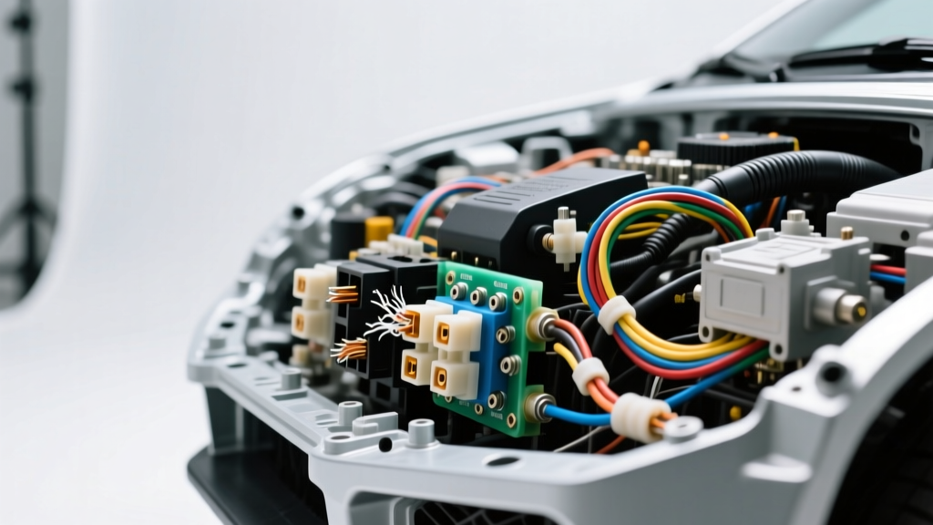
The Gap Between Textbook Theory and Shop-Floor Reality
Many technicians enroll in auto electrical courses to master multimeter diagnostics, CAN-Bus topology, and oscilloscope waveform analysis. While these programs provide an excellent foundation in Ohm's Law and basic circuit tracing, they frequently gloss over the high-current safety protocols, transient voltage spikes, and mechanical termination realities that cause real-world electrical fires and catastrophic module failures. A textbook might show a simple 12V relay circuit, but it rarely warns you about the 100V inductive kickback that will fry an ECU driver transistor if a flyback diode is missing.
At Autoflowwire, we bridge the gap between academic theory and heavy-duty automotive applications. Below are five critical wiring mistakes and safety hazards that standard auto electrical courses often fail to emphasize, complete with SAE standards, AWG specifications, and real-world troubleshooting data.
1. Undersizing Wire for High-Inrush Loads (Ignoring SAE J1127)
A common trap for beginners is applying steady-state Ohm's Law to high-inrush circuits like starter motors, diesel glow plug relays, or winch solenoids. A starter motor might draw 150A while cranking, but the initial inrush (locked rotor current) can spike to 400A+ for 200 milliseconds.
Many courses teach wire sizing based on standard primary wire charts, but they fail to differentiate between SAE J1128 (primary automotive wire) and SAE J1127 (heavy-duty battery cable). SAE J1128 wire is rated for lower continuous amperage and has different thermal dissipation properties. Using 4 AWG J1128 wire for a diesel starter circuit will result in severe voltage drop, often exceeding 0.8V under load. This voltage drop starves the PCM of the minimum 9.5V required to keep the fuel injector drivers active, causing the engine to stall during cranking.
SAE J1128 vs. J1127 Reference Chart
| AWG Size | SAE J1128 Max Ampacity | SAE J1127 Max Ampacity | Typical Application |
|---|---|---|---|
| 18 AWG | 6A | N/A | Sensors, CAN-Bus, Lighting |
| 14 AWG | 15A | N/A | Fuel Pump Relays, Horns |
| 10 AWG | 30A | N/A | Radiator Fan Low Speed |
| 4 AWG | 60A | 120A | Alternator B+ Output |
| 1/0 AWG | N/A | 250A | Starter Motor, Battery Grounds |
2. Ignoring Inductive Kickback on ECU Drivers
When you energize an inductive load—such as a fuel pump relay coil (e.g., Bosch 0 332 014 150), an AC compressor clutch, or a transmission shift solenoid—a magnetic field builds up around the coil windings. When the ECU's low-side driver opens the circuit to turn the component off, that magnetic field collapses rapidly. This induces a massive reverse-voltage spike (often -80V to -150V) that travels back into the ECU.
Standard auto electrical courses show relays with pins 30, 87, 85, and 86, but rarely stress the necessity of a flyback diode or snubber resistor. If you are wiring an aftermarket relay harness and connect the coil ground to the ECU driver pin without placing a 1N4007 flyback diode across pins 85 and 86 (cathode to 12V, anode to ground), the inductive spike will instantly punch through the ECU's internal Darlington transistor. Always use relays with integrated suppression resistors or diodes when controlled by solid-state module outputs.
3. The "Solder-Only" Splice and Vibration Fatigue
Soldering is often taught as the gold standard for electrical connections in basic electronics classes. However, in automotive environments, a solder-only wire splice is a severe reliability hazard. Solder wicks into the copper strands via capillary action, creating a rigid, brittle section of wire right at the edge of the insulation. Under constant engine bay vibration (10-50Hz) and thermal cycling (-40°C to 125°C), the wire experiences work hardening and fatigue, eventually snapping inside the insulation.
The Professional Standard: According to TE Connectivity automotive connector specifications and OEM wiring guidelines, all automotive splices must utilize a mechanical crimp (open-barrel or closed-barrel) to provide strain relief. If soldering is used for environmental sealing, it must be paired with a mechanical crimp, and the joint must be sealed with dual-wall, adhesive-lined heat shrink (such as 3M FP-301 or Raychem SCL) to prevent moisture ingress and galvanic corrosion.
4. High-Resistance Grounds and CAN-Bus Corruption
Technicians are taught that "ground is ground," leading to the dangerous habit of bolting ground eyelets to painted chassis points, strut towers, or anodized aluminum brackets. In high-current circuits, this causes voltage drop and heat. But in modern networked vehicles, a poor ground can corrupt the entire CAN-Bus network.
CAN-Bus relies on differential signaling: CAN-High operates between 2.5V and 3.5V, while CAN-Low operates between 1.5V and 2.5V. Both transceivers reference their local module ground. If a PCM ground (e.g., Pin 14 on a 16-way Metri-Pack 280 connector) has a 0.6V voltage drop due to a painted bolt hole, the transceiver's reference voltage shifts. The receiving module sees a skewed differential voltage, interprets it as a bit error, and throws a U0100 (Lost Communication with ECM/PCM) code.
- The Fix: Always use a ring terminal with an internal star washer to bite through paint and corrosion.
- The Test: Perform a voltage drop test across the ground circuit while the module is awake and under load. A healthy automotive ground should exhibit less than 0.10V drop.
5. Lethal Probing of Airbag (SRS) Squib Circuits
CRITICAL SAFETY WARNING: Never probe an airbag squib circuit with a standard multimeter or self-powered test light.
Airbag circuits are universally identified by yellow loom and yellow TE Connectivity or Deutsch connectors. These are not standard low-current sensor circuits; they are pyrotechnic ignition circuits. A standard deployment squib requires approximately 1.2 to 3.0 Amps for 10 to 50 milliseconds to ignite the sodium azide or guanidine nitrate propellant.
Many digital multimeters output enough current during a continuity or resistance test to inadvertently bridge the squib bridge-wire, causing the airbag to deploy in the technician's face. Furthermore, OEM yellow connectors feature internal shorting bars. When the connector is unplugged, a metal clip automatically shorts the two squib pins together. This ensures that if a stray voltage spike (from a nearby wiring short or static discharge) hits the harness, the current bypasses the airbag inflator entirely. Never attempt to back-probe these connectors, and always wait a minimum of 15 minutes after disconnecting the battery before working near the steering column clock spring or seat-mounted side airbags.
Summary: Elevating Your Electrical Standards
While auto electrical courses provide the essential vocabulary and theoretical framework for diagnosing modern vehicles, true mastery requires an understanding of the physical, thermal, and mechanical realities of automotive wiring. By respecting SAE cable standards, managing inductive kickback, executing proper mechanical crimps, ensuring zero-drop ground references, and treating SRS circuits with extreme caution, you transition from a textbook student to a master automotive electrical technician. Always consult OEM wiring diagrams and Bosch Mobility Solutions technical bulletins before modifying or repairing high-stakes vehicle networks.