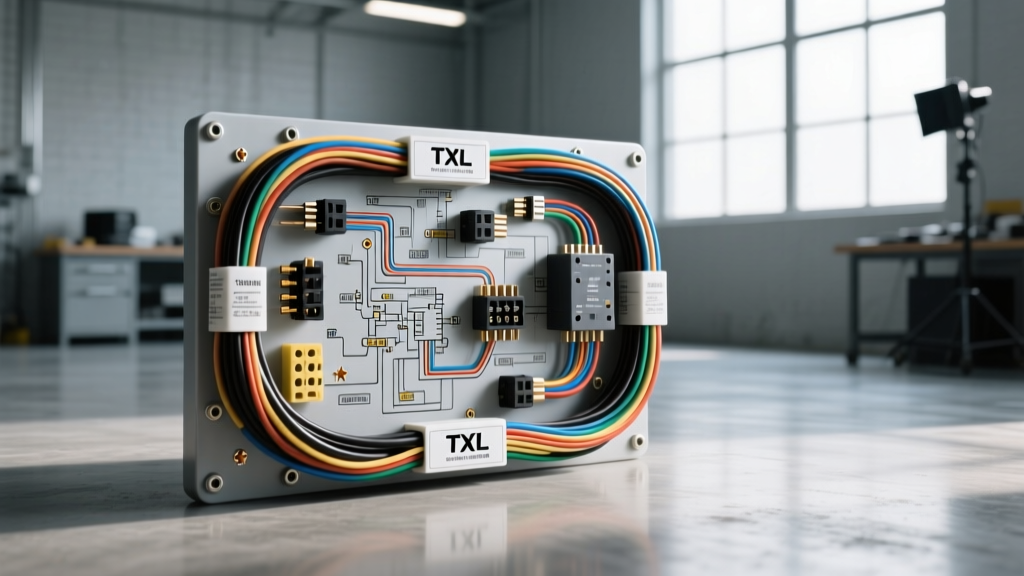
The Philosophy of a Custom Harness Upgrade
When tackling a classic car rewire or a high-performance restomod build, adopting the meticulous standards seen in top-tier regional shops—often referred to in builder circles as the Louis Auto Electric method—ensures long-term reliability, safety, and diagnostic clarity. Factory wiring from the 1960s and 1970s was designed for minimal electrical loads, typically supporting little more than a points-style ignition, a few incandescent bulbs, and a low-output alternator. Modern upgrades like electronic fuel injection (EFI), electric cooling fans, and high-voltage ignition systems easily exceed the capacity of aging copper and brittle PVC insulation.
The core tenets of the Louis Auto Electric approach prioritize oversized grounding, strict adherence to SAE wire standards, sealed connector systems, and centralized power distribution. This guide breaks down the exact methodology for designing and executing a custom harness upgrade that will withstand the harsh under-hood environment while delivering clean, noise-free voltage to sensitive engine management computers.
Phase 1: Electrical Load Audit and Alternator Sizing
Before cutting a single length of wire, you must perform a comprehensive electrical load audit. Undersizing the alternator or the main battery feed wire is the most common failure point in custom builds. Modern 1-Wire alternators are popular for their clean look, but high-amperage setups often require a 3-Wire configuration to sense voltage accurately at the battery and excite the rotor field properly.
| Component | Continuous Draw (A) | Peak/Surge Draw (A) | Recommended Main Wire (AWG) |
|---|---|---|---|
| EFI Fuel Pump (In-tank 255lph) | 12A | 18A | 10 AWG |
| Electric Cooling Fans (Dual 16') | 25A | 45A | 8 AWG |
| MSD Ignition Box (e.g., 6AL) | 15A | 20A | 10 AWG |
| Halogen Headlights (Pair) | 10A | 12A | 12 AWG (via relay) |
| ECU / Engine Management | 5A | 8A | 14 AWG |
| Power Windows & Accessories | 20A | 35A | 10 AWG |
For a typical restomod with EFI and dual fans, the continuous draw hovers around 80A, with peak surges exceeding 120A during initial fan startup. A minimum 130A alternator is required, paired with a 4 AWG main charge wire routed directly to the battery or a front-mounted Mega-Fuse distribution block.
Phase 2: Wire Selection and SAE J1128 Standards
Never use standard hardware store THHN or stranded PVC wire in an automotive application. PVC insulation becomes brittle when exposed to under-hood heat cycles and engine oil. The Louis Auto Electric standard mandates the use of cross-linked polyethylene (XLPE) insulated wire, specifically conforming to the SAE J1128 Low-Tension Primary Cable specification.
- TXL (Thin-wall Cross-Linked): Rated for 125°C. Features a thin insulation jacket, allowing for smaller harness diameters and tighter bend radii. Ideal for engine bay sensor wiring and tight firewall pass-throughs.
- GXL (General-purpose Cross-Linked): Rated for 125°C. Slightly thicker insulation than TXL, offering superior abrasion resistance for chassis routing and areas where the harness may flex against sheet metal.
| Circuit Type | Standard PVC Equivalent | TXL / GXL Required | Max Length (ft) before >0.5V Drop |
|---|---|---|---|
| Battery to Starter / Main Bus | 1/0 AWG | 1/0 AWG Welding Cable | 6 ft |
| Alternator Main Output | 8 AWG | 6 AWG TXL | 4 ft |
| Headlight Feed (Relay to Lamp) | 12 AWG | 14 AWG TXL | 10 ft |
| Dash / Gauges / ECU Sensors | 16 AWG | 18 AWG TXL | 15 ft |
Standard color coding should be strictly maintained to aid future diagnostics: Red for constant 12V+, Black for chassis/engine ground, Pink for switched ignition, Orange for accessory circuits, and Yellow for ECU memory/sensor returns.
Phase 3: Relay Logic and High-Amp Circuit Routing
Running high-amperage loads (like fuel pumps or cooling fans) directly through a dashboard switch or an ECU trigger pin is a guaranteed way to melt switches and fry engine management boards. The correct approach utilizes Bosch-style ISO mini relays to isolate the high-amp load from the low-amp trigger circuit.
Standard 30A Bosch Relay Pinout:
- Pin 30: 12V+ Input (fed directly from a fused battery source via 10 AWG wire).
- Pin 87: Output to the load (fuel pump, fan motor).
- Pin 85: Ground (tied to a clean chassis ground point).
- Pin 86: Switched 12V+ trigger (fed from the ignition switch, ECU output, or thermostat switch via 18 AWG wire).
- Pin 87a: Normally Closed (left unconnected in standard high-amp switching applications).
Always install an ATO/ATC blade fuse within 18 inches of the power source on the Pin 30 feed wire. If the wire chafes against the chassis before the relay, the fuse will blow, preventing an electrical fire.
Phase 4: Connector Selection for Hostile Environments
Soldering wires together and wrapping them in electrical tape is strictly prohibited in professional motorsports and high-end custom builds. Solder wicks into the wire strands, creating a rigid, brittle joint that will inevitably snap under engine vibration. Instead, use open-barrel crimpers and sealed connector systems. For deeper insights into crimping methodologies, reference the Painless Performance Wiring Guides.
- Delphi Weather-Pack: The industry standard for under-hood connections. Features silicone seals that withstand high heat and moisture. Available in 1.5mm and 2.4mm terminal sizes, handling up to 20A per pin. Ideal for headlights, horns, and alternator plugs.
- Metri-Pack 150 & 280: Compact, sealed connectors used extensively by OEMs for EFI sensors (TPS, MAP, IAT, O2). The 150 series handles up to 14A, while the 280 series is used for higher-current injector feeds.
- Deutsch DT Series: The ultimate choice for high-vibration, high-heat zones like transmission solenoid harnesses and exhaust-mounted O2 sensor pigtails. Rated for 13A per pin with a rugged thermoplastic shell and secondary locking wedges.
For all heat-shrink applications on battery lugs and alternator rings, use dual-wall, adhesive-lined heat shrink with a 3:1 shrink ratio. The inner wall melts and seals the wire strands, preventing moisture ingress and copper oxidation.
Phase 5: The Star Ground Architecture
The most common cause of erratic EFI behavior, flickering gauges, and alternator whine in audio systems is poor grounding. Daisy-chaining grounds from one accessory to another creates varying voltage potentials, which the ECU interprets as sensor noise. The Louis Auto Electric method relies on a centralized Star Ground system.
- Mount a 1/4-inch thick copper bus bar in a central, accessible location on the firewall or inner fender.
- Run individual ground wires from every major engine bay component (EFI pump relay, ignition box, ECU, sensors) directly to this bus bar.
- Connect the bus bar to the engine block and the chassis using oversized 1/0 AWG braided copper straps.
- Prepare all grounding surfaces by sanding down to bare, shiny metal. Remove all paint, powder coat, and rust.
- Apply a thin layer of anti-oxidant paste (such as Noalox or Penetrox-E) to the bare metal before attaching the ring terminal. This displaces oxygen and prevents future corrosion without hindering electrical conductivity.
- Torque all ground studs to 15-20 ft-lbs to ensure maximum surface area contact.
Phase 6: Firewall Pass-Through and Loom Routing
When routing the main harness through the firewall, never simply drill a hole and push the wires through. Sheet metal edges will slice through TXL insulation within weeks due to engine torque roll and chassis flex. Use a reinforced rubber firewall grommet or a CNC-machined billet firewall pass-through plate. Always create a 'drip loop'—a downward U-shape in the wire before it enters the grommet—to ensure that water running down the harness drips off the bottom of the loop rather than flowing directly into the cabin or engine bay junctions.
For harness protection, avoid cheap corrugated plastic split-loom in high-heat areas, as it melts and traps moisture against the wire. Instead, use expandable braided PET sleeving for general chassis routing, and fiberglass or silicone-coated sleeving (rated for 1000°F) anywhere the harness passes within 12 inches of exhaust headers or the EGR system.
Conclusion: Validation and Testing
Once the harness is fully routed, crimped, and secured with adhesive-backed P-clips (spaced no more than 18 inches apart), the final step is validation. Do not rely solely on a test light. Use a digital multimeter to verify voltage drop across every major circuit under load. A healthy circuit should exhibit less than 0.2V of drop from the battery positive terminal to the load, and less than 0.1V from the load ground to the battery negative terminal. By adhering to these rigorous standards, your custom build will feature an electrical architecture that is not only reliable but a work of engineering art.