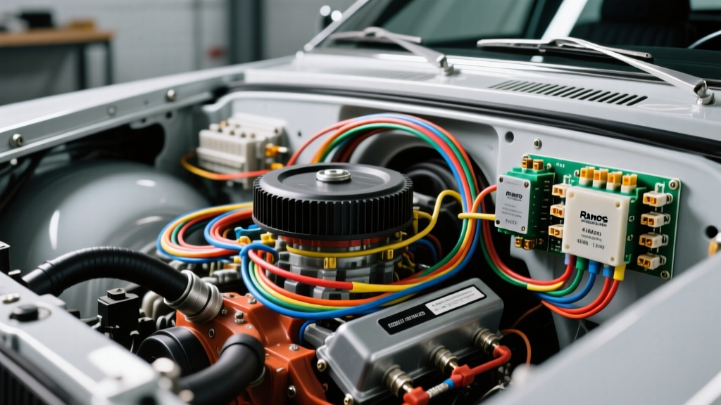
The Ramos Auto Electric Restomod Standard
When executing a high-amp restomod build or an EV-swap conversion, adopting the Ramos Auto Electric wiring philosophy ensures your vehicle's electrical architecture can handle modern accessory loads without catastrophic voltage drops. The Ramos Auto Electric methodology moves away from brittle, cloth-covered OEM wires and standard PVC insulation, favoring instead XLPE (Cross-linked polyethylene) insulated, high-strand count tinned copper wire. This upgrade path is critical for classic muscle cars and vintage trucks that originally featured 40-amp to 60-amp alternators and glass-tube fuse panels, which are entirely inadequate for modern electric fuel pumps, EFI systems, and electric AC compressors.
In this comprehensive upgrade guide, we break down the core principles of a high-amp restomod wiring project, detailing exact AWG sizing, terminal crimping standards, and relay integration for high-draw accessories. Whether you are rebuilding a chassis harness from scratch or upgrading specific high-current circuits, these specifications will align your build with top-tier custom auto electric standards.
Core Architecture: Upgrading to a 140A+ Alternator Circuit
The foundation of any Ramos Auto Electric style upgrade is replacing the factory 10SI or 1-wire 63-amp alternator with a modern high-output unit, such as a Powermaster 140A+ alternator. To support this increased output, the main charging wire must be upgraded to handle continuous high-amperage without generating excess heat, which increases resistance and reduces charging efficiency at the battery.
Main Power Wire Routing and AWG Selection
For runs exceeding 4 feet from the alternator B+ terminal to the main distribution busbar or battery positive post, 1/0 AWG fine-strand welding cable is mandatory. Standard SAE stranded wire often lacks the flexibility required for tight engine bay routing and can suffer from strand breakage under harmonic engine vibration. According to the SAE J1128 Standard for low-tension primary cable, XLPE insulation is rated for continuous temperatures up to 125°C (257°F), vastly outperforming standard PVC (105°C) near exhaust headers.
| Wire Gauge (AWG) | Strand Count | Max Continuous Amps | Recommended Application | Terminal Type |
|---|---|---|---|---|
| 1/0 AWG | 4,533 (30 AWG strands) | 190A | Alternator B+ to Battery / Main Busbar | 3/8" Copper Lug (Adhesive Lined) |
| 4 AWG | 1,666 (30 AWG strands) | 120A | Busbar to Mega Fuse / Starter Solenoid | 5/16" Copper Lug |
| 8 AWG | 655 (30 AWG strands) | 70A | Electric AC Compressor / High-Draw Fans | Delphi Weather-Pack / Ring Terminal |
| 12 AWG | 65 (24 AWG strands) | 25A | EFI Relays / Fuel Pump / Ignition Coils | Deutsch DT / Metri-Pack 280 |
Torque Specifications and Termination
A common failure mode in restomod alternator circuits is a loose B+ terminal nut, which causes arcing and melts the alternator casing. The alternator B+ terminal nut must be torqued to exactly 85-110 in-lbs (7-9 ft-lbs). Always use an adhesive-lined, dual-wall heat shrink over the copper lug to prevent moisture ingress and galvanic corrosion, a hallmark of the Ramos Auto Electric weatherproofing standard.
Fuse Box and Relay Block Integration
Upgrading from a glass-tube fuse panel to a modern ATO/ATC blade fuse block with integrated relay sockets is non-negotiable for high-draw modifications. The main power feed from the battery or alternator should first pass through a 150A MEGA or AMEG fuse mounted within 18 inches of the power source, as recommended by Painless Performance Wiring Manuals for main circuit protection.
High-Draw Accessory Relays
Never route high-amperage loads (like electric cooling fans or fuel pumps) through the ignition switch or dashboard toggles. Instead, use a centralized relay block. Use 30A or 40A Bosch-style ISO mini relays. The control side of the relay (Pins 85 and 86) should be wired with 16 AWG wire, while the load side (Pins 30 and 87) must utilize 10 AWG or 12 AWG wire depending on the specific accessory draw.
Electric AC Compressor and High-Draw Accessory Wiring
One of the most complex upgrades in a modern restomod is the installation of an electric AC compressor, such as a standalone 12V brushless compressor or an engine-driven compressor with a high-amperage magnetic clutch. Unlike vintage R4 compressors that drew minimal clutch current (approx. 3-4 amps), modern heavy-duty AC clutches and electric compressor inverters can draw 15A to 30A continuously.
Dedicated Relay Circuits and Pin Configurations
When wiring an electric AC compressor clutch or inverter, a dedicated 40A relay circuit is required. The power feed must be sourced directly from the main distribution busbar, protected by a 30A ATC blade fuse. Refer to the MGI SpeedWare Harness Building Guide for proper loom management when routing wires near the compressor pulley to prevent abrasion.
| Relay Pin | Function | Wire Color Code | Wire Gauge | Connection Point |
|---|---|---|---|---|
| Pin 30 | Constant 12V Power Input | Red (with 30A Inline Fuse) | 10 AWG | Main ATC Fuse Block Busbar |
| Pin 87 | Switched 12V Output to Load | Blue | 10 AWG | AC Compressor Clutch / Inverter |
| Pin 86 | Switched 12V Trigger Signal | Yellow | 16 AWG | HVAC Dashboard Switch / Binary Safety Switch |
| Pin 85 | Relay Coil Ground | Black | 16 AWG | Local Chassis Ground (Ring Terminal) |
Pro-Tip: When wiring the binary or trinary safety switch for the AC system, ensure the trigger wire (Yellow) passes through the low/high-pressure cut-off switch before reaching Pin 86. This ensures the compressor disengages instantly if refrigerant pressure drops or spikes, protecting both the compressor and the electrical system from catastrophic failure.
The 5-Point Grounding Matrix Strategy
A hallmark of premium custom auto electrical work is the grounding matrix. Relying on rusty, 40-year-old factory ground straps will cause ECU resets, flickering headlights, and erratic fuel pump behavior. Implement a dedicated 5-point grounding strategy using 2 AWG tinned copper strap:
- Ground 1: Engine Block to Chassis Frame Rail (Use 2 AWG, bolted to a clean, bare metal surface with a star washer).
- Ground 2: Alternator Case to Engine Block (Ensure the alternator mounting brackets are bare metal; paint acts as an insulator).
- Ground 3: Engine Block to Battery Negative Post (1/0 AWG main negative cable).
- Ground 4: Chassis Frame to Vehicle Body/Cab (2 AWG strap across the firewall or body mounts).
- Ground 5: Battery Negative Post to Chassis Frame Rail (1/0 AWG).
Always use a wire brush or flap disc to remove paint, powder coat, and rust down to bare, shiny metal before attaching any ground ring terminal. Apply a thin layer of dielectric grease over the terminal after tightening to prevent oxidation.
Troubleshooting Common Restomod Voltage Drops
Even with meticulous wiring, voltage drops can occur if connections are improperly crimped. Use a Digital Multimeter (DMM) set to DC Volts to perform a voltage drop test across every major connection while the system is under load (e.g., engine running, AC compressor engaged, cooling fans on).
Voltage Drop Testing Procedure
- Place the red DMM probe on the alternator B+ terminal and the black probe on the battery positive post.
- With the engine at 2,000 RPM and accessories on, the DMM should read no more than 0.2V. A reading higher than 0.2V indicates excessive resistance in the main charging cable or a failing crimp at the copper lug.
- Repeat the test on the ground side: Place the red probe on the alternator case and the black probe on the battery negative post. The acceptable drop is 0.1V or less.
- If testing the Electric AC Compressor relay circuit, measure across the relay contacts (Pin 30 to Pin 87) while engaged. A drop exceeding 0.3V indicates pitted internal relay contacts; replace the relay immediately.
Conclusion
Executing a restomod wiring upgrade using the Ramos Auto Electric methodology transforms a classic vehicle's electrical system from a fragile, outdated network into a robust, high-amperage architecture capable of supporting modern EFI, electric AC compressors, and high-output audio systems. By strictly adhering to XLPE wire standards, utilizing proper AWG sizing, implementing centralized relay blocks, and executing a flawless 5-point ground matrix, you ensure reliable, spark-free operation for decades to come.