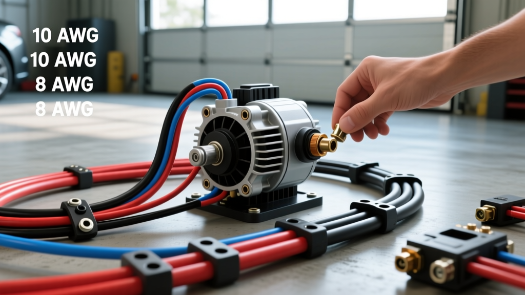
The A&A Auto Electrical Upgrade Philosophy
When executing high-draw automotive electrical modifications, adopting the A&A Auto Electrical methodology ensures long-term reliability under extreme thermal and vibrational stress. Professional auto electrical shops prioritize voltage stability, minimized circuit resistance, and mil-spec material selection over cosmetic wiring. For overlanding, towing, and mobile command builds, the factory charging system is rarely sufficient. Upgrading to a high-output alternator and reinforcing the primary B+ and ground networks requires strict adherence to DC wiring standards, precise crimping techniques, and intelligent dual-battery isolation.
This guide details the complete fabrication and installation of a 220-amp charging system, utilizing the A&A Auto Electrical benchmark for harness routing, circuit protection, and smart solenoid integration.
Core Component Selection: 220A GM 12SI High-Output Stator
While modern vehicles utilize PCM-controlled alternators (like the GM AD244 or Denso SC4), complex CAN-bus integrations often reject high-amperage aftermarket units without custom ECM tuning. The A&A Auto Electrical standard for universal and retrofit upgrades relies on the GM 12SI high-output platform. The 12SI case is robust, widely supported, and features an internal voltage regulator that operates independently of the vehicle's ECU.
For a 220A continuous output rating, the alternator must feature a high-density hairpin stator and heavy-duty diode heat sinks. Standard 6-diode rectifiers will fail under sustained 180A+ loads; therefore, ensure your unit utilizes a 12-diode bridge configuration to distribute thermal loads evenly across the rectifier assembly.
Heavy-Duty Harness Fabrication to SAE J1128 Standards
The most common failure point in amateur high-amp upgrades is the use of consumer-grade PVC-insulated wire and stamped battery clamps. Professional auto electrical builds mandate compliance with SAE J1128 Low Tension Primary Cable specifications, specifically GXL or TXL cross-linked polyethylene (XLPE) insulation.
Wire Gauge and Insulation Selection
XLPE insulation offers superior resistance to under-hood heat (up to 150°C) and abrasion compared to standard PVC (rated to 105°C). Furthermore, the thinner wall thickness of GXL wire allows for easier routing through tight firewall grommets and engine bays.
| Circuit Function | AWG Size | Max Length (12V) | Insulation Type | Terminal Style |
|---|---|---|---|---|
| Alternator B+ to Battery | 1/0 AWG | 8 Feet | GXL (Red) | Hex-Crimp Ring, 5/16" |
| Main Chassis Ground | 1/0 AWG | 4 Feet | GXL (Black) | Hex-Crimp Ring, 3/8" |
| Regulator Sense Wire | 10 AWG | 15 Feet | GXL (Yellow) | Deutsch DT Pin |
| Exciter / Dash Lamp | 14 AWG | 10 Feet | GXL (Blue) | Spade Connector |
Terminal Crimping and Environmental Sealing
Do not use hammer crimpers or pliers for 1/0 AWG terminals. Use a dedicated hydraulic or ratcheting hex-crimp tool. A proper hex crimp cold-welds the copper strands to the terminal barrel, eliminating air pockets where moisture can infiltrate and cause galvanic corrosion. After crimping, seal the terminal barrel with dual-wall polyolefin heat shrink containing an inner adhesive lining to create a watertight environmental seal.
Precision Regulator Wiring and Remote Sense Routing
The GM 12SI alternator utilizes a 2-pin connector on the voltage regulator. Properly wiring these pins is the difference between a system that maintains 14.4V at the battery and one that undercharges due to voltage drop across the harness.
- Pin 1 (Exciter/Lamp): This pin requires 12V to "wake up" the regulator. In a true 1-wire setup, a jumper wire connects Pin 1 directly to the B+ output post. However, this causes the alternator to spin up immediately upon engine cranking, placing heavy drag on the starter motor. The A&A Auto Electrical method routes Pin 1 through a 12V ignition-switched relay, ensuring the alternator only begins charging once the engine is running.
- Pin 2 (Sense): This is the most critical wire. Pin 2 dictates the target voltage. If left disconnected, the regulator senses voltage at the alternator's B+ post. If there is a 0.6V drop across the main B+ cable, the battery will only see 13.8V. You must route a 10 AWG yellow sense wire from Pin 2 directly to the positive terminal of the main starting battery. This sense wire should be protected by a 15A inline ATC fuse located within 7 inches of the battery positive post.
The Big Three Ground Network
Upgrading the positive B+ cable is useless if the return path (ground) is bottlenecked by factory braided straps that corrode and fray. The "Big Three" upgrade replaces the primary ground paths with 1/0 AWG GXL wire.
- Alternator Case to Chassis: The alternator grounds through its mounting brackets. Paint, powder coat, and rust act as insulators. Scrape all mounting surfaces to bare metal and apply a conductive anti-seize compound. Run an additional 1/0 AWG strap directly from the alternator casing to the nearest clean chassis point.
- Engine Block to Chassis: Replace the factory ground strap with a 1/0 AWG cable, securing it to the engine block using a heavy-duty starter bolt or dedicated brass ground boss.
- Engine Block to Battery Negative: Ensure the main negative cable is free of corrosion and securely torqued to the battery post (5-7 Nm).
Dual Battery ML-ACR Integration
For builds requiring a secondary house battery, the A&A Auto Electrical standard rejects cheap thermal-style isolators due to their inherent 0.7V diode drop. Instead, use a smart Automatic Charging Relay (ACR), such as the Blue Sea Systems 7622 ML-ACR. The ML-ACR uses a bi-stable magnetic latching relay that draws zero continuous current while holding the batteries together.
ML-ACR Wiring Pinout
- Stud A (Start Battery): Connect to the main starting battery positive via 1/0 AWG.
- Stud B (House Battery): Connect to the auxiliary battery positive via 1/0 AWG.
- Ground (GND): Connect to a clean chassis ground using 10 AWG.
- Ignition Signal (IGN): Connect to a 12V ignition-switched source. This prevents the ACR from combining batteries when the vehicle is off and a solar panel or battery charger is active on the house bank.
Following ABYC E-11 DC Electrical Standards—widely adopted in high-end automotive and marine builds—ensure every positive cable within 7 inches of the battery terminal is protected by a Class T fuse or MRBF (Marine Battery Fuse) terminal block.
Validation and Voltage Drop Testing
Once the harness is loomed, secured with UV-resistant split loom, and terminated, the system must be validated using a digital multimeter (DMM) capable of measuring millivolts.
Voltage Drop Decision Tree
- Test B+ Cable: Place the red DMM probe on the alternator B+ post and the black probe on the battery positive post. Start the engine and turn on all high-draw accessories (headlights, HVAC blower, rear defrost). The reading should be less than 0.15V. If higher, the crimp is faulty or the wire gauge is insufficient.
- Test Ground Network: Place the red probe on the battery negative post and the black probe on the alternator casing. Under load, the reading must be less than 0.10V. Higher readings indicate poor surface contact at the mounting brackets or a failing ground strap.
- Test Sense Wire: Measure voltage directly at the battery posts. It should read exactly 14.2V to 14.4V. If it reads lower, verify the 10 AWG yellow sense wire has continuity to Pin 2 on the regulator.
By adhering to these A&A Auto Electrical protocols, your high-output charging system will deliver clean, stable DC power to sensitive inverters, winches, and auxiliary lighting without the risk of thermal runaway or voltage starvation.