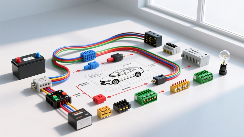
Mastering Auto Electrical Symbols for Diagnostic Flows
Staring at a complex factory wiring diagram without understanding the underlying symbology is like trying to read a technical manual in a foreign language. Modern vehicle electrical architectures rely on standardized glyphs defined by the Society of Automotive Engineers (SAE) and the International Organization for Standardization (ISO). For an automotive technician or advanced DIYer, recognizing these auto electrical symbols is only the first step; the true expertise lies in using those symbols to build a logical, step-by-step troubleshooting flow.
Instead of randomly poking at wires with a multimeter, a professional uses the schematic as a roadmap. In this guide, we will decode the most critical auto electrical symbols and apply them to a real-world diagnostic scenario: tracing a failed engine cooling fan circuit from the battery to the chassis ground.
Essential SAE and ISO Auto Electrical Symbols Reference
Before diving into the diagnostic flow, you must be able to instantly identify the core components on a schematic. Below is a reference table of the most frequently encountered auto electrical symbols and their real-world equivalents.
| Symbol Name | Visual Representation | Real-World Component | Diagnostic Action |
|---|---|---|---|
| Battery / Power Source | Two parallel lines (one thick, one thin) or a stack of cells | 12V Lead-Acid Battery, UBEC B+ Stud | Verify resting voltage (12.6V) and perform load test. |
| Fuse / Fusible Link | S-curve inside a rectangle, or a simple zigzag line | MAXI, ATO, or Mini blade fuse | Check continuity or test for B+ on both test points. |
| Relay Coil | Rectangle with diagonal lines or a looped coil symbol | Bosch-style mini relay pins 85 & 86 | Measure coil resistance (typically 60-90 ohms). |
| Switch / Relay Contact | Angled line with a dot (Normally Open or Closed) | Relay pins 30 & 87, ignition switch | Check for voltage drop (<0.1V) across contacts when closed. |
| Chassis Ground | Line ending in hash marks or a downward-pointing triangle | Ring terminal bolted to body/paint-free metal | Perform voltage drop test from battery negative to ground point. |
| Diode | Triangle pointing to a perpendicular line | Flyback suppression diode, alternator rectifier | Test for unidirectional continuity (OL in reverse bias). |
| Splice / Connection | Solid black dot where wires intersect | Soldered joint, ultrasonic weld, or crimp connector | Inspect for corrosion, green crust, or pulled pins. |
Step-by-Step Troubleshooting Flow: The Cooling Fan Circuit
To demonstrate how to read auto electrical symbols in action, let us troubleshoot a common issue: a primary radiator cooling fan that fails to engage when the engine reaches 220°F (104°C). We will follow the circuit from the power source to the ground, using the schematic symbols to dictate our testing sequence.
Step 1: Trace the Power Source and Fuse Symbol
Every circuit begins at a power source symbol. On our schematic, we see the battery symbol leading to a 40A MAXI fuse symbol located in the Underhood Bussed Electrical Center (UBEC). The wire leaving the fuse is designated as 10 AWG Red (RED).
- The Test: Set your digital multimeter (DMM) to DC Volts. Probe the exposed test points on top of the 40A MAXI fuse. You should read battery voltage (approx. 12.6V) on both sides.
- Failure Mode: If you have 12.6V on one side but 0V on the other, the fuse is blown. However, a 40A fuse rarely blows without a reason. Before replacing it, check the 10 AWG Red wire for chafing against the radiator support or a seized fan motor drawing excessive amperage.
Step 2: Decode the Relay Coil and Control Circuit
Following the schematic, the 10 AWG Red wire feeds into Pin 30 of the relay contact symbol. However, the relay will not switch without the control circuit. The schematic shows the relay coil symbol connected to Pins 85 and 86. Pin 85 receives Ignition-run voltage via an 18 AWG Pink (PNK) wire. Pin 86 is the control side, routed back to the Powertrain Control Module (PCM) via an 18 AWG Dark Green (DK GRN) wire.
- The Test: Back-probe the relay connector. With the ignition ON, verify 12V at Pin 85. Next, command the fan ON using a bidirectional OBD2 scan tool. The PCM completes the circuit by providing a ground path. Probe Pin 86; it should drop to near 0V when commanded.
- Failure Mode: If Pin 86 stays at 12V during the command, the PCM internal driver transistor may have failed, or there is an open circuit in the 18 AWG DK GRN wire. Always check the wire for breaks before condemning a $400 PCM.
Step 3: Analyze the Switch Contact Symbol
When the PCM grounds Pin 86, the electromagnetic field pulls the internal armature, closing the switch contact symbol between Pin 30 and Pin 87. Pin 87 feeds the fan motor via a 12 AWG Dark Blue (DK BLU) wire.
- The Test: This is where voltage drop testing is critical. With the relay energized and the fan attempting to run, place your DMM leads across Pin 30 (input) and Pin 87 (output). A healthy relay contact symbol should show a voltage drop of less than 0.1V.
- Failure Mode: If you read a 2.5V drop across the contacts, the internal relay armature is pitted or carbon-fouled. The relay is starving the fan motor of voltage, causing it to overheat and fail prematurely. Replace the Bosch-style mini relay immediately.
Step 4: Verify the Ground Symbol and Termination
The current flows through the fan motor and exits via a 12 AWG Black (BLK) wire, terminating at the chassis ground symbol (designated as G104 on most GM schematics). This symbol represents a physical ring terminal bolted to the vehicle's sheet metal or subframe.
- The Test: Leave the DMM on DC Volts. Place the black lead on the battery's negative post and the red lead on the metal ring terminal of G104 while the fan is commanded ON. A reading above 0.1V indicates excessive resistance at the ground point.
- Failure Mode: Grounds are the most common failure point in auto electrical systems. If G104 is corroded, loose, or bolted over paint, the fan will run slowly or not at all. Remove the M6 bolt, wire-brush the chassis contact patch to bare metal, apply dielectric grease, and torque to 10 Nm (89 lb-in).
Advanced Symbols: Diodes, Resistors, and Network Lines
As you move from simple 12V circuits to modern multiplexed networks, the auto electrical symbols become more complex. Understanding these is vital for preventing catastrophic module damage during diagnostics.
The Flyback Diode Symbol
Many modern relay schematics include a diode symbol wired in parallel with the relay coil (pins 85 and 86), with the cathode line pointing toward the positive feed. When a relay coil is de-energized, the collapsing magnetic field generates a massive reverse voltage spike (inductive kickback) that can exceed 100V. The flyback diode safely routes this spike back into the coil. If you bypass a relay with a diode symbol using a standard non-diode relay, the voltage spike will eventually destroy the PCM's internal low-side driver.
Resistor and CAN Bus Symbols
When troubleshooting network communication, you will encounter the resistor symbol (a jagged line or an IEC standard rectangle). In a Controller Area Network (CAN), you will see two 120-ohm resistor symbols located at the physical ends of the CAN-High and CAN-Low twisted pair. If your OBD2 scanner fails to communicate with the ECM, measuring the resistance between CAN-H and CAN-Low at the Data Link Connector (DLC) should yield exactly 60 ohms (the parallel equivalent of the two 120-ohm terminating resistors). If you read 120 ohms, one of the network resistor symbols represents an open circuit or a disconnected module.
Conclusion
Reading auto electrical symbols is not just about memorizing shapes; it is about understanding the physical behavior of the components those shapes represent. By treating every symbol as a specific testing checkpoint, you transform a chaotic wiring harness into a predictable, step-by-step diagnostic flow. Always verify your schematic against factory service data, keep your multimeter calibrated, and never skip the voltage drop test.