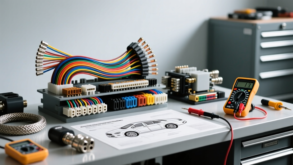
The Foundation of the Rudy's Auto Electric Diagnostic Standard
The evolution of modern vehicle electrical architectures has transformed the 12-volt system from a simple ignition and lighting network into a complex, high-amperage data and power grid. When dealing with high-output charging systems, bespoke off-road harnesses, and severe parasitic draw issues, generic troubleshooting falls short. This is where the Rudy's Auto Electric methodology becomes the industry benchmark. Originating from decades of specialist bench-testing and custom bay fabrication, the Rudy's Auto Electric standard prioritizes empirical voltage drop testing, non-invasive CAN-bus parasitic draw isolation, and mil-spec harness termination. This advanced technical deep dive explores these core principles, providing actionable wiring specifications, AWG sizing matrices, and diagnostic protocols for high-demand automotive electrical systems.
High-Output Alternator Wiring: Upgrading the B+ Circuit
When upgrading from a factory 140A alternator to a high-output 250A+ unit (such as those used in severe-duty towing, off-road lighting, or competition audio applications), the factory 8 AWG or 6 AWG B+ charge wire becomes a critical bottleneck. According to the SAE J1128 Standard for low-tension primary cable, pushing 250 amps through 6 AWG wire over a standard 6-foot run will result in excessive voltage drop and severe thermal degradation. The Rudy's Auto Electric protocol mandates a complete replacement of the primary charge cable using SGT or SGX type welding cable.
Specification Matrix: Alternator Output vs. Minimum Wire Gauge
| Alternator Peak Output | Minimum AWG (Up to 8 ft) | Minimum AWG (8-15 ft) | Recommended Terminal Type |
|---|---|---|---|
| 140A - 180A | 4 AWG | 2 AWG | Standard Ring Terminal |
| 190A - 250A | 2 AWG | 1/0 AWG | Heavy-Duty Copper Lug |
| 275A - 350A+ | 1/0 AWG | 2/0 AWG | Hydraulic Crimp Lug |
The Sense Wire Protocol
A common failure point in high-amp upgrades is the alternator voltage sense wire. Factory systems often pull sense voltage from the ignition switch or a nearby fuse block. Under high-load conditions, voltage drop between the battery and the fuse block can cause the alternator's internal regulator to overcharge, pushing system voltage past 15.2V and boiling the battery electrolyte. The Rudy's Auto Electric method requires routing a dedicated 10 AWG sense wire directly from the alternator's sense terminal to the battery's positive terminal or the main chassis distribution block, protected by an inline 15A Maxi fuse within 6 inches of the battery source.
The Voltage Drop Matrix: Alternator to Battery Testing
Rejecting 'battery voltage' as a primary diagnostic metric is a core tenet of advanced auto-electric troubleshooting. A multimeter reading 14.2V at the battery does not guarantee the alternator is functioning correctly if the B+ cable is suffering from internal corrosion. The Rudy's Auto Electric methodology relies strictly on dynamic voltage drop testing under loaded conditions.
- Preparation: Set the digital multimeter (DMM) to the DC millivolt (mV) scale. Turn on all major electrical loads (headlights, HVAC blower on high, rear defroster) to force the alternator into maximum output.
- Positive Circuit Test: Place the red probe on the alternator's B+ output terminal and the black probe on the battery's positive post. A reading above 100mV (0.10V) indicates excessive resistance in the positive charge cable, terminal crimps, or distribution blocks.
- Ground Circuit Test: Place the red probe on the alternator's aluminum casing (ensure bare metal contact) and the black probe on the battery's negative post. A reading above 50mV (0.05V) indicates a poor alternator case-to-engine ground. Note: Alternators must be grounded through their mounting brackets; adding a secondary ground strap from the alternator case to the chassis is often required in high-vibration or powder-coated bracket setups.
Non-Invasive Parasitic Draw: The Fuse Voltage Drop Technique
Modern vehicles feature complex CAN-bus and LIN-bus networks that can take up to 45 minutes to enter 'sleep mode.' The traditional method of pulling fuses to isolate a parasitic draw will repeatedly wake up the vehicle's control modules, resetting the sleep timer and masking the offending circuit. The Rudy's Auto Electric standard utilizes the non-invasive Fuse Voltage Drop method to identify parasitic draws without interrupting circuit continuity.
Executing the Fuse Drop Method
With the vehicle asleep and the DMM set to DC millivolts, place the probes across the two test points on the top of standard ATO/ATC blade fuses in the interior and under-hood fuse panels. As current flows through the fuse, the internal element creates a minute voltage drop proportional to the amperage draw. Using the chart below—derived from Painless Performance Products engineering data—technicians can calculate the exact amperage draw of each circuit without breaking the connection.
ATO/ATC Fuse Voltage Drop to Amperage Reference
| Fuse Rating | 10mA Draw (mV Drop) | 25mA Draw (mV Drop) | 50mA Draw (mV Drop) | 100mA Draw (mV Drop) |
|---|---|---|---|---|
| 5 Amp | 1.5 mV | 3.8 mV | 7.5 mV | 15.0 mV |
| 10 Amp | 0.8 mV | 2.0 mV | 4.0 mV | 8.0 mV |
| 15 Amp | 0.5 mV | 1.3 mV | 2.6 mV | 5.2 mV |
| 20 Amp | 0.4 mV | 1.0 mV | 2.0 mV | 4.0 mV |
Note: Acceptable parasitic draw for modern vehicles with telematics and keyless entry is typically between 30mA and 50mA. Any circuit exhibiting a draw above 100mA after the 45-minute sleep cycle is the primary suspect.
Alternator Diode Ripple Testing via Oscilloscope
While a multimeter can verify DC voltage output, it cannot detect failing alternator diodes that leak AC voltage into the DC system. AC ripple can severely interfere with sensitive engine control unit (ECU) sensors, particularly 5V reference circuits and crankshaft position sensors. The Rudy's Auto Electric diagnostic suite mandates an oscilloscope ripple test for any vehicle presenting unexplained sensor codes or audio system alternator whine.
- Scope Setup: Connect the scope probe to the battery positive terminal and the ground to the battery negative. Set the vertical scale to 100mV/division and the timebase to 5ms/division.
- AC Coupling: Switch the oscilloscope channel to AC coupling to block the 14V DC baseline and isolate the AC ripple.
- Threshold Analysis: A healthy alternator with intact diode trio and stator windings will display a peak-to-peak AC ripple of less than 50mV (0.050V). If the ripple exceeds 100mV, or if the waveform shows flat spots indicating a dropped phase, the alternator requires immediate bench rebuild or replacement.
Bespoke Harness Fabrication: Connector and Termination Standards
The longevity of any custom automotive wiring harness is dictated by its terminations. The Rudy's Auto Electric methodology strictly prohibits the use of solder in high-vibration, under-hood environments. Solder creates a rigid point of stress concentration that inevitably leads to copper fatigue and wire breakage just behind the solder joint. Instead, high-quality, gas-tight mechanical crimps are mandated.
Weather-Pack and Metri-Pack Integration
For sensor and actuator circuits, the industry standard relies on Delphi Automotive Connection Systems (now Aptiv) Metri-Pack 280 series connectors. These connectors utilize a primary lock (the terminal tang) and a secondary lock (TPA - Terminal Position Assurance) to prevent backing out under vibration. When fabricating custom extensions, technicians must use the correct cavity plugs (silicone dummy pins) for any unused ports to maintain the IP67 weather-tight seal and prevent moisture ingress and galvanic corrosion.
Deutsch DT Series for High-Current Accessories
For aftermarket lighting bars, winch solenoids, and electric cooling fans drawing 15A to 30A, the Deutsch DT series is the preferred connector. Utilizing a solid stainless steel retention clip and silicone rear grommets, the DT series withstands extreme under-hood temperatures and pressure washing. Proper termination requires stripping the 12 AWG or 14 AWG wire exactly 5/16 of an inch, crimping the nickel-plated copper barrel, and inserting the pin into the housing until the audible 'click' confirms the retention clip engagement.
Conclusion
Mastering the Rudy's Auto Electric methodology requires a fundamental shift from reactive part-swapping to proactive, empirical electrical validation. By adhering to strict AWG sizing matrices for high-amp charging systems, utilizing non-invasive fuse voltage drop techniques for CAN-bus parasitic draws, and enforcing mil-spec crimping standards for harness fabrication, technicians can eliminate the electrical gremlins that plague modern and custom vehicles. True auto-electric expertise lies not in the tools you own, but in the rigorous, repeatable diagnostic protocols you apply to every circuit you touch.