The Yakima Valley Overland & Agricultural Electrical Demand
The Yakima Valley and the broader Central Washington region present a unique set of challenges for automotive electrical systems. From the dust-choked washboard roads of the Wenas Wildlife Area to the heavy agricultural loads required for local farming operations, vehicle electrical architectures in this region must be exceptionally robust. When outfitting a Toyota Tacoma, 4Runner, or Jeep Wrangler for overland expeditions or heavy-duty work, the factory alternator and battery configurations are rarely sufficient. Upgrading to a dual-battery system, integrating a DC-DC charger, and installing auxiliary fuse blocks require precision, high-quality materials, and specialized tooling. Whether you are searching for a professional auto electric Yakima specialist or planning a comprehensive DIY build, understanding the true costs and tool requirements is critical to avoiding catastrophic voltage drops or electrical fires.
Professional vs. DIY: Auto Electric Yakima Cost Breakdown
Labor rates for specialized automotive electrical work in the Pacific Northwest typically range from $130 to $175 per hour. A complete overland electrical overhaul—including a dual-battery isolator, a 30A DC-DC charger (such as the Redarc BCDC1230D), and a marine-grade auxiliary fuse panel—often requires 12 to 18 hours of bench and vehicle time. Below is a comparative analysis of hiring a local shop versus executing a DIY installation.
| Installation Component | Professional Shop Cost (Yakima Avg.) | DIY Cost (Parts & Tools) |
|---|---|---|
| Dual Battery Tray & Hardware | $350 - $450 | $250 (e.g., National Luna or DIY aluminum) |
| DC-DC Charger & Isolator Wiring | $600 - $900 (Labor) | $0 (Your own labor) |
| 1/0 AWG Cable & Lugs | $150 (Marked up) | $85 (Pure copper, marine grade) |
| Specialized Tooling Investment | N/A | $250 - $400 (One-time purchase) |
| Total Estimated Cost | $1,600 - $2,400+ | $900 - $1,100 |
While the DIY route offers significant savings, it demands a strict adherence to SAE J1128 wiring standards and an investment in professional-grade crimping and testing equipment. Cutting corners on tools is the primary cause of high-resistance connections, which lead to melted insulation and alternator burnout.
Essential Tooling for High-Current Automotive Wiring
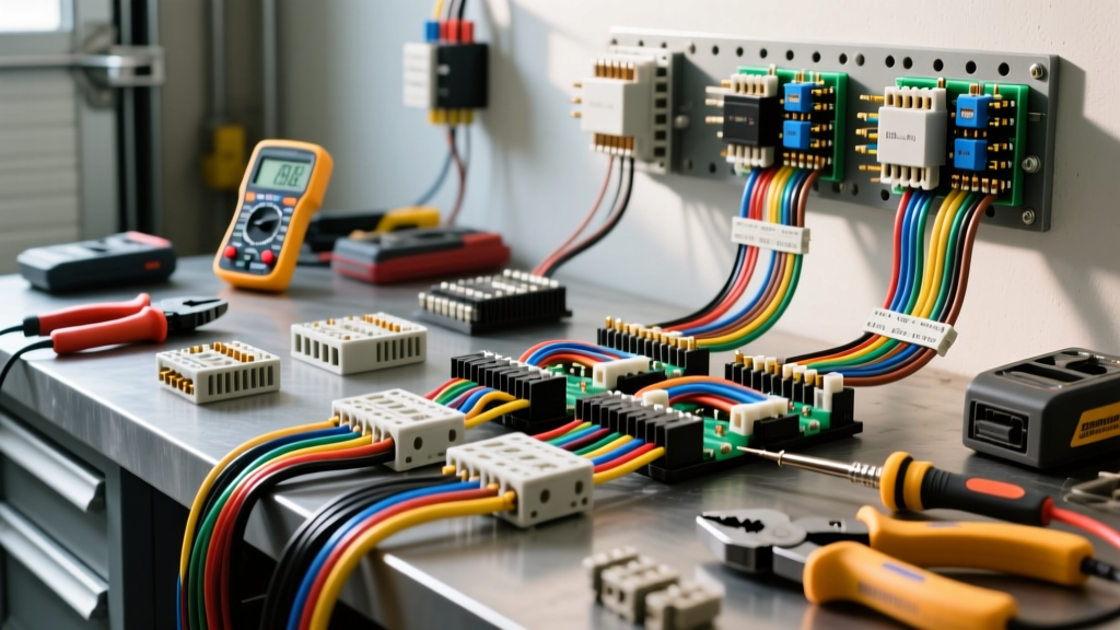
To replicate the quality of a top-tier auto electric shop, your workbench must be equipped with tools capable of handling heavy-gauge wire and precision diagnostic testing. Standard hardware store crimpers will deform 1/0 AWG lugs, leading to hot spots under heavy winching or inverter loads.
- Hydraulic Lug Crimper (1/0 to 4/0 AWG): A tool like the TEMCo Hydraulic Crimper or the Milwaukee M18 FORCE LOGIC ensures a perfect hexagonal crimp. Hexagonal crimps distribute mechanical stress evenly, which is vital for surviving the high-frequency vibrations of off-road trails near Rimrock Lake.
- Ratcheting Crimper for Open Barrel Terminals (10-22 AWG): The Knipex 97 53 14 or equivalent is mandatory for crimping Deutsch and AMP Superseal terminals. A ratcheting mechanism ensures the crimp cycle is fully completed before releasing, preventing under-crimped pins that can back out of connector housings.
- True RMS Digital Multimeter & Load Tester: A Fluke 87V or Power Probe IV is required to measure voltage drop under load. Testing a circuit with no load will not reveal a high-resistance crimp.
- Heat Shrink Torch & Marine-Grade Adhesive Shrink: Standard electrical tape degrades in the extreme summer heat of the Yakima Valley. You must use dual-wall, adhesive-lined heat shrink (e.g., 3M MDT) to create a waterproof, corrosion-proof seal at every terminal.
Technical Blueprint: Dual-Battery & DC-DC Architecture
When designing the electrical architecture for an overland rig, wire sizing must account for the total length of the circuit (positive AND negative return paths) and the ambient temperature under the hood. According to Blue Sea Systems engineering guidelines, SAE wire has a slightly smaller copper cross-section than standard AWG, requiring careful derating for long runs to the rear of a truck bed.
| Circuit Application | Wire Gauge (SAE/AWG) | Protection (Fuse Type & Rating) | Wire Color Code |
|---|---|---|---|
| Starter Battery to VSR Isolator | 1/0 AWG | 250A MIDI Fuse | Red (Primary Positive) |
| VSR Isolator to Aux Battery | 1/0 AWG | 250A MIDI Fuse | Red (Primary Positive) |
| DC-DC Charger Input (from Alt) | 6 AWG | 60A ANL Fuse | Red (Fused Positive) |
| DC-DC Charger Ignition Trigger | 16 AWG | 5A ATC Inline Fuse | Yellow (Switched 12V+) |
| Aux Fuse Block Main Feed | 8 AWG | 40A ATC / Circuit Breaker | Red (Fused Positive) |
| Chassis Ground Bus to Battery | 2 AWG | N/A | Black (Primary Ground) |
Torque Specifications and Terminal Preparation
A common failure point in DIY builds is improper terminal torque. When securing 3/8" ring terminals to a battery post or heavy-duty busbar, the torque specification is typically 10 to 12 ft-lbs (120 to 144 in-lbs). Over-torquing can strip the threads on lead-acid battery posts or crack lithium BMS terminals, while under-torquing allows micro-movements that generate arc flashes and heat. Always apply a thin layer of di-electric grease or No-Ox-Id A-Special to copper and aluminum busbar connections to prevent galvanic corrosion, especially in agricultural environments where fertilizer dust is prevalent.
Connector Selection for High-Dust & High-Vibration Environments
The Yakima region is notorious for fine, abrasive dust that infiltrates engine bays and trailer connections. Standard spade connectors and twist-lock plugs will fail rapidly. For auxiliary lighting, winch controls, and camper tie-ins, you must utilize environmentally sealed connectors.
- Deutsch DT Series: The industry standard for off-road lighting and sensors. Rated for IP6K9K (high-pressure washdown and total dust ingress protection). Pin Configuration: In a standard 2-pin DT plug, Cavity 1 is designated for Positive (Red wire) and Cavity 2 for Ground (Black wire). Always use the proper insertion/extraction tool to avoid damaging the silicone rear seal.
- Anderson Powerpole (APP): Ideal for high-current (50A to 120A) detachable connections, such as portable fridge slides or trailer feeds. The genderless housing design and stainless steel leaf springs ensure constant contact pressure, mitigating voltage drop caused by vibration.
Troubleshooting Voltage Drop in Auxiliary Circuits
If your DC-DC charger is underperforming or your auxiliary lights are dimming, you likely have a voltage drop issue. A healthy automotive charging system should maintain 13.8V to 14.4V at the alternator. If the DC-DC charger input reads below 13.0V while the engine is running, follow this diagnostic decision tree:
- Test the Source: Measure voltage directly at the alternator B+ terminal and the engine block ground. If it reads 14.2V, the charging system is healthy.
- Test the Isolator/Charger Input: Measure voltage at the input stud of the DC-DC charger while it is under maximum load (charging a depleted battery). If the voltage drops to 12.5V, you have a 1.7V drop in the supply cable.
- Isolate the Fault (Positive vs. Negative):
- Place the multimeter's red probe on the alternator B+ and the black probe on the DC-DC charger positive input. A reading above 0.2V indicates excessive resistance in the positive cable, fuse holder, or crimp lugs.
- Place the red probe on the DC-DC charger negative terminal and the black probe on the alternator casing. A reading above 0.1V indicates a poor chassis ground or undersized negative return wire.
- Inspect Crimps: High resistance is almost always located at the crimp joint. Cut away the heat shrink and inspect the copper. If it appears green or black, moisture breached the seal, requiring the cable to be replaced.
Summary: Achieving Professional Results
Whether you ultimately hire an auto electric Yakima professional or tackle the build yourself, the physics of high-current 12V systems remain unchanged. Success relies on oversized copper conductors, hexagonal hydraulic crimps, sealed connectors, and rigorous voltage-drop testing. By investing in the correct tooling and adhering to SAE and ABYC standards, you can build an electrical architecture capable of surviving the harshest conditions the Pacific Northwest has to offer, ensuring your rig remains powered and reliable miles off the grid.
For further reading on marine and off-grid electrical standards, refer to the Overland Journal Electrical Systems Guide and ABYC E-11 AC/DC electrical guidelines.