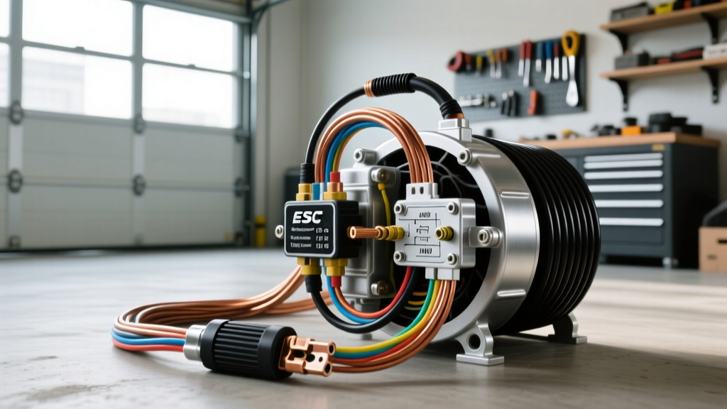
Defining a Real Auto Electric Climate Upgrade
When enthusiasts and custom fabricators discuss a real auto electric conversion, they are not simply swapping in a 12V radiator fan or an electric water pump. A true electric vehicle (EV) swap or engine-off climate control retrofit requires completely rethinking the accessory drive, starting with the air conditioning system. Engine-driven swashplate compressors are obsolete in these builds. Instead, the industry standard is the 12V or 24V hermetic scroll compressor driven by a brushless DC (BLDC) motor. This guide details the exact electrical, mechanical, and thermodynamic protocols required to install, wire, and commission a 12V electric scroll compressor for automotive applications.
System Specifications and Electrical Requirements
Unlike traditional magnetic-clutch compressors, 12V scroll compressors rely on an Electronic Speed Controller (ESC) or integrated inverter to convert DC battery power into the 3-phase AC power required by the BLDC motor. Understanding the electrical load is critical before cutting any wire.
| Component | Specification | Wire Gauge (AWG) | Connector Type |
|---|---|---|---|
| Main Power Feed (B+) | 12V DC, 40A Max Continuous | 8 AWG SAE J1128 Copper | Ring Terminal (M8 Stud) |
| Ground Return (B-) | Chassis / Battery Direct | 8 AWG SAE J1128 Copper | Ring Terminal (M8 Stud) |
| ESC Signal Input | 0-5V PWM (1kHz - 5kHz) | 18 AWG TXL Shielded | 4-Pin Deutsch DT |
| Thermostat Trigger | 12V Low Amp Enable | 16 AWG GXL | Weather-Pack 2-Way |
Step 1: Mechanical Mounting and NVH Isolation
Hermetic scroll compressors generate high-frequency vibration that differs significantly from the low-frequency harmonics of a belt-driven piston compressor. Mounting the unit directly to the chassis or firewall will result in severe Noise, Vibration, and Harshness (NVH) transfer into the cabin. Fabricate a dedicated subframe using 1/8-inch steel or 6061-T6 aluminum. Isolate the compressor from the subframe using Shore 60A polyurethane bobbin mounts. When securing the compressor to the isolation mounts, torque the M8 mounting hardware to exactly 25 Nm (18.5 lb-ft). Over-torquing will crush the rubber isolators, defeating their dampening properties, while under-torquing risks harmonic loosening.
Step 2: Routing the High-Current DC Power Circuit
The inrush current (Locked Rotor Amps, or LRA) on a 3000W 12V scroll compressor can momentarily exceed 80A during startup, while running amps (RLA) stabilize around 25A to 30A. You must use 8 AWG stranded copper wire that meets SAE J1128 Primary Cable Standards. Do not use copper-clad aluminum (CCA) wire, as its higher resistance will cause severe voltage drop under load.
Install a 50A MIDI or Mega fuse within 18 inches of the positive battery terminal. Avoid ANL fuses in the engine bay; their exposed fusible elements are prone to atmospheric corrosion and vibration-induced fatigue. Route the 8 AWG red (B+) and black (B-) cables through the firewall using a sealed rubber grommet. Maintain a strict minimum 4-inch separation from any EFI ignition coil harnesses or CAN-bus data lines to prevent Electromagnetic Interference (EMI) from the ESC's high-frequency switching.
Step 3: Crimping and Termination Standards
Do not rely on cheap, stamped metal connectors or solder-only joints for the 8 AWG power feed. The high continuous amperage will cause poorly crimped terminals to oxidize, creating a high-resistance thermal bottleneck that can melt the insulation. Use a dedicated hex-crimp or H-frame die tool for all heavy-gauge ring terminals. For the Deutsch DT signal connectors, ensure the silicone wire seals are inserted over the 18 AWG wire before crimping the barrel. Always use the specific DT insertion tool to seat the pins into the housing until you hear an audible click. A partially seated pin will arc under the 5V PWM load, eventually melting the connector housing and destroying the ESC.
Step 4: ESC Signal Wiring and EMI Mitigation
The ESC requires a clean Pulse Width Modulation (PWM) signal to dictate compressor RPM. A standard 12V binary thermostat switch will not work; you must use a digital climate controller with a PWM step-down output, or install a 12V-to-5V PWM signal converter. The standard 4-pin Deutsch DT signal pinout is as follows:
- Pin 1 (PWM Signal In): 18 AWG Shielded (Blue). Carries the 0-5V duty cycle command.
- Pin 2 (Signal Ground): 18 AWG Shielded (Black). Must tie directly to the ESC ground, not a random chassis ground.
- Pin 3 (Tachometer Out): 18 AWG (Green). Open-collector feedback for RPM monitoring.
- Pin 4 (Enable/Standby): 18 AWG (Yellow). 12V trigger to wake the inverter logic board.
Because the ESC generates significant EMI, the PWM signal wire must be shielded. Ground the shield drain wire at the controller end only to prevent ground loops.
Step 5: Dielectric Oil and Refrigerant Protocols
This is where most engine-swap builders destroy their compressors. Engine-driven compressors rely on PAG (Polyalkylene Glycol) oil. PAG oil is highly hygroscopic and electrically conductive. Introducing PAG oil into a hermetic electric compressor will cause the internal BLDC motor windings to short to the aluminum casing, instantly destroying the inverter. Electric scroll compressors require specific POE (Polyol Ester) oil or specialized dielectric ND-Oil (such as ND-Oil 11). POE oil provides the necessary lubrication for the scroll tips while maintaining a high dielectric breakdown voltage. Refer to Mobile Air Conditioning Society (MACS) guidelines for exact POE viscosity matching based on your refrigerant choice (R134a or R1234yf).
Step 6: Voltage Drop Testing and Evacuation
Before charging the system with refrigerant, perform a dynamic voltage drop test. With the ESC commanded to 100% duty cycle (maximum RPM), measure the voltage directly at the battery terminals, and then measure it at the ESC power input pins. Any voltage drop exceeding 0.5V on the power side or 0.2V on the ground side indicates excessive resistance. A voltage drop of just 1V at the ESC will cause the inverter to derate compressor speed, resulting in poor cabin cooling and premature motor overheating. Once the electrical circuit passes, pull a deep vacuum to 500 microns to ensure system integrity before charging.
Real-World Troubleshooting: Inverter Fault Codes
Most 12V scroll compressors feature an integrated LED diagnostic indicator on the ESC housing. If the compressor fails to engage, count the LED flashes to diagnose the fault:
| LED Blinks | Fault Condition | Corrective Action |
|---|---|---|
| 2 Flashes | Over-Voltage / Under-Voltage | Check alternator output; verify battery voltage is between 11.5V and 15.5V. |
| 3 Flashes | Over-Current / Stall | System overcharged with refrigerant; check condenser fan operation and high-side pressure. |
| 4 Flashes | Loss of PWM Signal | Check 18 AWG signal wire continuity; verify digital thermostat is outputting 1kHz-5kHz frequency. |
| 5 Flashes | Internal Inverter Temp High | ESC is overheating; ensure compressor is not mounted near exhaust headers; verify POE oil level. |
For comprehensive safety standards regarding modern refrigerants in custom electric setups, always consult the SAE J2842 R1234yf Guidelines to ensure your fittings and manifold gauges are compatible with the system pressure and environmental requirements.