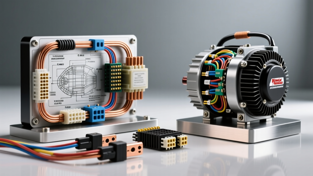
Evaluating High-Output Charging Systems and Wiring Architecture
Upgrading a vehicle's electrical architecture requires more than simply bolting on a higher-amperage alternator. When dealing with severe-duty electrical loads, regional specialists like Fondy Auto Electric in Appleton often set the benchmark for diagnosing parasitic draws and upgrading charging systems to handle extreme temperature swings and heavy accessory loads. Whether you are outfitting a work truck with high-draw lighting, upgrading an off-road vehicle for heavy winching, or simply replacing a failing OEM unit, selecting the right alternator and pairing it with the correct wire gauge and terminal hardware is critical. A 200-amp alternator is useless if the factory 8 AWG charge wire bottlenecks the current, causing severe voltage drop and potential fire hazards.
This guide provides a comprehensive product comparison and selection framework for high-output alternators, heavy-duty wiring harnesses, and vibration-resistant connectors, utilizing the rigorous diagnostic standards expected from top-tier auto electrical professionals.
Alternator Selection: OEM Replacement vs. High-Output Upgrades
The first step in any charging system upgrade is matching the alternator's output curve to the vehicle's specific amperage demands. Factory alternators are typically rated for maximum output at high RPMs (often above 2,500 rotor RPM), which translates to roughly 1,200 to 1,500 engine RPM depending on the pulley ratio. If your vehicle spends most of its time idling or in stop-and-go traffic, an OEM unit will fail to keep up with high-draw accessories like electric cooling fans, auxiliary lighting, or high-end audio amplifiers.
Product Comparison Matrix: Charging System Options
| Alternator Type | Typical Output (Idle / Max) | Regulator Type | Best Application | Case Size / Mounting |
|---|---|---|---|---|
| OEM Denso Hairpin | 90A / 140A | Internal (LIN Bus) | Daily driving, stock accessories | Compact, direct bolt-on |
| Powermaster Street/Strip | 110A / 150A | Internal 1-Wire | Mild performance, quick charge recovery | GM 10-SI / 12-SI footprint |
| Mechman High-Output (370A Series) | 220A / 370A | Internal / External Sense | Severe duty, winching, massive audio | Large Case (requires bracket mods) |
Understanding the Denso 3-Pin Regulator Connector
When retaining an OEM-style Denso alternator but upgrading the wiring harness, understanding the regulator pinout is mandatory. The most common failure mode in aftermarket harness installations is miswiring the sense circuit, which causes the alternator to overcharge or undercharge based on voltage drop at the alternator B+ terminal rather than the battery.
- Pin L (Lamp/Excitation): Provides the initial excitation current to the rotor. Typically connected to a switched 12V source through a dashboard indicator lamp or a resistor (usually 470 ohms) to prevent back-feeding.
- Pin IG (Ignition): Switched 12V signal that 'wakes up' the internal voltage regulator when the key is in the ON position.
- Pin S (Sense): The most critical pin for high-output setups. This must be wired directly to the positive battery terminal using a dedicated 14 AWG or 12 AWG fused sense wire. If wired to the alternator B+ post, the regulator will compensate for voltage drop across the charge cable by pushing system voltage dangerously high (often exceeding 15.5V), boiling the battery electrolyte.
Wire Gauge Selection for High-Amperage Circuits
According to SAE J1141 standards for automotive electrical cables, wire sizing must be calculated based on the maximum continuous current draw and the total length of the circuit (positive and ground combined). The goal is to maintain a voltage drop of less than 3% (0.43V on a 14.4V charging system) across the entire cable run.
The 'Big Three' Wiring Upgrade Specifications
The 'Big Three' upgrade involves replacing or supplementing the three main ground and power cables in the engine bay. This is a standard procedure recommended by auto electrical experts to eliminate grounding bottlenecks that cause dimming headlights and erratic ECU behavior.
| Circuit Path | Minimum AWG (Up to 150A) | Recommended AWG (200A+) | Wire Type | Hardware / Torque Specs |
|---|---|---|---|---|
| Alternator B+ to Battery Positive | 4 AWG | 1/0 AWG | Stranded Copper (SGT/SGX) | 3/8" Ring Terminal, 12-15 ft-lbs |
| Engine Block to Chassis Ground | 4 AWG | 2 AWG | Stranded Copper (SGT/SGX) | 5/16" Ring, clean to bare metal |
| Battery Negative to Chassis Ground | 4 AWG | 1/0 AWG | Stranded Copper (SGT/SGX) | 3/8" Ring Terminal, 12-15 ft-lbs |
Note: SGT (Standard Gauge Thermoplastic) and SGX (Cross-linked) battery cables are required. Do not use standard THHN building wire, as it lacks the fine stranding necessary to withstand engine bay vibration and will eventually suffer from strand breakage and internal corrosion.
Terminal and Connector Selection for Vibration Resistance
Regional shops operating in areas with harsh winters and rough road conditions, much like the standards upheld by Powermaster's technical guidelines, emphasize that the terminal connection is the weakest link in any high-current circuit. A poorly crimped 1/0 AWG lug will generate immense heat under a 150-amp load, melting the insulation and causing a short.
Crimping and Sealing Methodology
- Strip Length: Strip exactly enough insulation so the wire strands are flush with the end of the copper barrel. Do not leave exposed copper outside the crimp zone, which invites galvanic corrosion.
- Tool Selection: For 4 AWG and larger, a hydraulic crimping tool with hexagonal dies is mandatory. Mechanical ratchet crimpers often fail to achieve the necessary cold-weld compression on heavy-gauge copper.
- Sealing: Never use vinyl electrical tape or standard thin-wall heat shrink. You must use dual-wall adhesive-lined heat shrink (often containing polyamide hot melt adhesive). When heated, the inner adhesive melts and flows into the wire strands, creating a watertight seal that prevents capillary action from drawing moisture under the insulation.
Sensor and Low-Current Connector Upgrades
For alternator sense wires, tachometer signals, and temperature sensors, spade terminals and butt splices are strictly prohibited in professional builds. Instead, utilize sealed connector systems:
- Delphi Metri-Pack 280 Series: Ideal for alternator regulator pigtails and sensor extensions. Features a secondary lock (TPA - Terminal Position Assurance) to prevent pins from backing out under vibration.
- Deutsch DT Series: The gold standard for auxiliary lighting relays and winch control solenoids. Utilizes solid copper contacts with silicone rear seals that are entirely waterproof and highly resistant to automotive fluids.
Diagnostic Benchmarks: Voltage Drop Testing
After installing the upgraded alternator and heavy-duty wiring, the system must be validated using a voltage drop test. Relying solely on a multimeter reading at the battery terminals is insufficient, as it does not reveal resistance hidden within the circuit connections.
To perform a proper voltage drop test across the new 1/0 AWG charge wire:
- Set your digital multimeter to DC Volts.
- Start the engine and turn on maximum electrical loads (headlights, HVAC blower on high, rear defroster) to force the alternator into maximum output.
- Place the red probe directly on the alternator B+ output stud (not the cable ring terminal).
- Place the black probe directly on the battery positive post (not the clamp).
According to Mechman Alternators and general SAE diagnostic protocols, a voltage drop reading exceeding 0.2V DC indicates excessive resistance. If your reading is 0.4V or higher, you have a faulty crimp, a corroded terminal surface, or an undersized cable. The connection must be disassembled, the terminal surface cleaned with a wire brush, and re-torqued to the manufacturer's specification.
Summary: Building a Resilient Electrical Architecture
Whether you are sourcing components through specialized distributors or relying on the diagnostic expertise of regional professionals like Fondy Auto Electric in Appleton, the principles of automotive electrical upgrades remain universal. Success relies on matching the alternator's output curve to the vehicle's duty cycle, sizing the wiring based on total circuit length rather than just amperage, and utilizing adhesive-sealed, hydraulically crimped terminals. By adhering to these strict selection and installation criteria, you ensure a charging system that delivers stable voltage, protects sensitive ECU modules, and withstands the harshest environmental conditions.