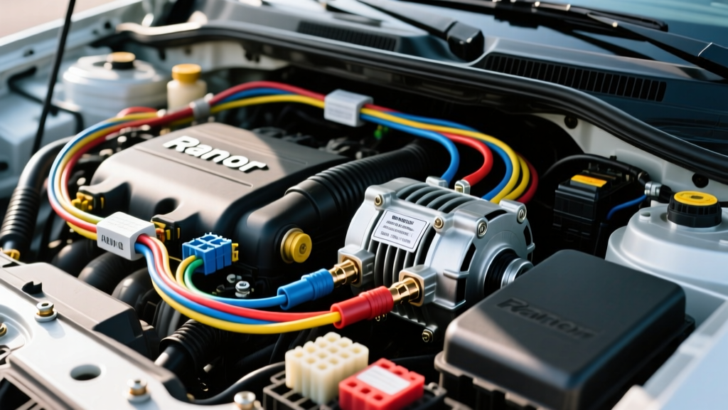
Introduction to Ranor Auto Electric High-Output Systems
Upgrading your vehicle's charging system is essential when running high-draw accessories like winches, heavy off-road lighting, or massive car audio amplifiers. The Ranor Auto Electric 250A High-Output Alternator paired with their Smart Charge Wiring Harness provides a robust, reliable solution for demanding electrical architectures. Unlike standard internally regulated units, the Ranor system utilizes an external smart regulator to optimize charge profiles based on battery chemistry and temperature.
This practical how-to guide details the exact installation procedures, wire sizing requirements, and pinout configurations necessary to safely integrate a Ranor Auto Electric alternator into your vehicle's 12V DC network. Proper execution of these steps ensures maximum alternator lifespan and prevents catastrophic wiring harness fires.
Pre-Installation: Tools and Wire Sizing Specifications
Before unbolting your factory alternator, you must gather the correct materials. High-amperage charging systems require strict adherence to SAE J1128 standards for low-tension primary cable to handle continuous thermal loads. Do not use standard copper-clad aluminum (CCA) wire; only pure OFC (Oxygen-Free Copper) stranded wire is acceptable for the B+ feed.
| Component | Specification | Notes |
|---|---|---|
| Main B+ Charge Cable | 1/0 AWG (53.5 mm²) OFC | Must be fine-strand welding cable for flexibility. |
| Main Overcurrent Protection | 300A Class T Fuse | Class T offers high AIC (Ampere Interrupting Capacity) for fast-blow protection. |
| Alternator B+ Terminal Nut | M8 x 1.25 Flange Nut | Grade 8 or stainless steel. Torque to 12-15 Nm. |
| Smart Regulator Harness | 16 AWG TXL Wire | TXL offers thin insulation and high heat resistance. |
| Crimp Terminals | Heavy-Duty Tinned Copper | Requires hex-crimp die, NOT indent crimp. |
Step 1: Mechanical Mounting and Case Isolation
The physical installation of the Ranor Auto Electric alternator requires precise alignment to prevent serpentine belt deflection. High-amp alternators generate significant heat; therefore, ensuring adequate airflow around the casing is critical.
- Disconnect the negative battery terminal and isolate it with a non-conductive boot.
- Remove the factory alternator and clean the mounting bracket ears with a wire wheel to ensure a pristine ground path. The alternator case grounds through the mounting brackets. If your vehicle uses powder-coated brackets, you must sand away the coating at the contact points.
- Install the Ranor alternator. Thread the mounting bolts by hand to avoid cross-threading the aluminum casing.
- Torque the main pivot bolt to 54 Nm (40 lb-ft) and the adjustment bracket bolt to 25 Nm (18 lb-ft).
Step 2: Routing the 1/0 AWG B+ Power Cable
The most common failure point in high-output charging systems is an undersized or poorly routed B+ cable. The Ranor 250A alternator can sustain 220A continuously at cruising RPMs, which will melt standard 4 AWG factory wiring in minutes.
Cable Routing and Crimping
- Route the 1/0 AWG red welding cable from the alternator B+ post to the positive battery terminal, avoiding exhaust manifolds and steering shafts.
- Use adhesive-lined marine-grade heat shrink over your crimps. The hex-crimp die must compress the terminal uniformly without piercing the copper strands.
- Install the 300A Class T fuse holder on the positive cable. Per Mad Electrical best practices, the main fuse must be located within 18 inches of the battery positive terminal to protect the entire cable run in the event of a short to ground.
- Connect the cable to the alternator B+ terminal and torque the M8 nut to 14 Nm. Over-tightening will strip the brass terminal post; under-tightening will cause arcing and localized melting.
Step 3: Wiring the 4-Pin Smart Regulator Harness
The Ranor Auto Electric external smart regulator uses a 4-pin Deutsch DT connector to manage the alternator's field current. Incorrect pinout wiring will result in either zero charging output or unregulated full-fielding, which will boil your battery and destroy the vehicle's ECU.
Ranor 4-Pin Regulator Pinout Configuration
| Pin | Wire Color | Function | Connection Point |
|---|---|---|---|
| 1 | Red (16 AWG) | Ignition (IGN) | 12V+ Switched ignition source (ECU relay or fuse box). |
| 2 | Blue (16 AWG) | Battery Sense | Direct to Battery Positive Post (NOT the fuse box or starter). |
| 3 | Black (16 AWG) | Ground (GND) | Direct to Battery Negative Post or clean engine block ground. |
| 4 | Yellow (16 AWG) | Exciter / Field | Connects directly to the alternator 'F' or 'EXC' spade terminal. |
Critical Warning: The Blue Battery Sense wire must read true battery voltage. If you connect it to the fuse box, the voltage drop across the factory wiring will trick the regulator into overcharging the battery to compensate for the perceived loss. Run a dedicated 16 AWG blue wire directly to the battery's positive lead, fused at 5A near the battery.
Step 4: Grounding and Alternator Case Isolation
While the alternator grounds primarily through its mounting brackets, high-amperage setups benefit from a dedicated case ground. This prevents stray AC ripple current from passing through the engine block and interfering with sensitive sensors like the crankshaft position sensor (CKP) or oxygen sensors.
- Locate the dedicated ground lug on the rear casing of the Ranor alternator.
- Attach a 4 AWG black OFC ground strap from this lug directly to the vehicle's chassis or the negative battery terminal.
- Apply dielectric grease to the terminal connection to prevent galvanic corrosion between the copper lug and the aluminum casing.
Troubleshooting Common Ranor Harness Faults
Even with meticulous installation, electrical gremlins can occur. Use a digital multimeter (DMM) to perform the following diagnostic checks if the system fails to charge correctly.
Symptom: Alternator Output is Stuck at 12.6V (No Charge)
- Cause: Loss of Ignition (IGN) signal or blown 5A sense fuse.
- Fix: Probe Pin 1 (Red wire) at the regulator connector with the key in the 'ON' position. You should read 12.2V or higher. If 0V, trace the ignition feed back to the fuse box.
Symptom: Overcharging (Voltage exceeds 14.8V on Lead-Acid)
- Cause: High resistance on the Blue Battery Sense wire.
- Fix: Perform a voltage drop test on the sense circuit. Place the DMM positive lead on the battery positive post and the negative lead on Pin 2 of the regulator harness. With the engine running and loads applied, the voltage drop should be less than 0.05V. If higher, replace the sense wire or clean the battery terminal connection.
Symptom: Excessive AC Ripple at the Battery
- Cause: Failed internal diode trio or poor case grounding.
- Fix: Switch your DMM to AC Volts. Place the leads across the battery terminals. A healthy Ranor Auto Electric system should show less than 50mV (0.050V) AC. Readings above 100mV indicate a bad diode or a missing dedicated case ground strap.
Final System Validation
Once all connections are secured and double-checked against the pinout table, reconnect the main battery negative terminal. Start the engine and measure the DC voltage at the battery posts. The Ranor smart regulator should initiate a bulk charge phase, displaying 14.2V to 14.4V for standard flooded lead-acid batteries, or up to 14.7V for AGM batteries. Turn on high-draw accessories like radiator fans and headlights; the voltage should not dip below 13.5V at idle, confirming the 250A output capability is fully realized.
For comprehensive standards on automotive electrical testing and wire ampacity, always refer to the latest SAE J1171 and manufacturer-specific service documentation. Proper installation of your Ranor Auto Electric components guarantees a resilient, high-capacity charging system ready for the most extreme automotive environments.