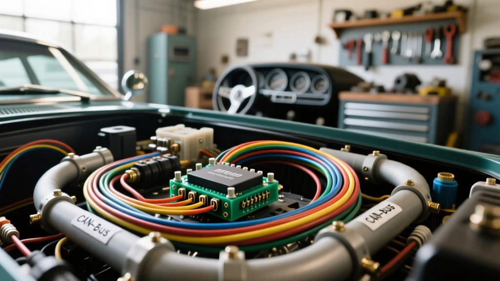
The Restomod Electrical Bottleneck
Swapping a modern powertrain into a classic chassis is a rite of passage for automotive enthusiasts, but the electrical system is where most DIY restomod projects fail. A classic 1960s or 1970s vehicle was designed to handle a mere 40 to 60 amps of total electrical load, powering little more than a distributor, a few incandescent bulbs, and an AM radio. Modern engine management systems, electric fuel pumps, and CAN-bus networks demand upwards of 150 amps and require pristine signal integrity. When undertaking a complex classic Mopar or GM restomod, studying the meticulous harness fabrication methods championed by specialized shops—such as the benchmark standards seen at Pettys Auto Electrical Services—can save you from catastrophic ECU failures, erratic sensor readings, and parasitic draws.
This guide breaks down the professional-grade wiring strategies required for high-amperage EFI swaps, focusing on power distribution, EMI suppression, and CAN-bus topography.
Main Power Distribution and High-Amp Alternator Routing
The foundation of any reliable restomod is the main power distribution block. Factory classic alternator charge wires (typically 10 AWG or 8 AWG) will instantly bottleneck a modern 140A to 200A alternator, leading to severe voltage drop, melted insulation, and potential electrical fires. According to SAE J1128 standards for low-tension primary cables, wire gauge must be selected based on both amperage and the total length of the circuit to mitigate voltage drop below 0.5V.
The 1/0 AWG Alternator Upgrade
For alternators outputting over 120 amps, upgrade the main charge wire to 1/0 AWG stranded copper welding cable. Unlike standard primary wire, fine-strand welding cable offers superior flexibility and lower resistance. Route this cable directly from the alternator B+ terminal to a 175A Mega Fuse located within 18 inches of the battery positive terminal, and then to the main power distribution busbar. Use adhesive-lined dual-wall heat shrink (3:1 shrink ratio) on all ring terminals to prevent moisture ingress and corrosion, which is a leading cause of high-resistance failures in under-hood environments.
ECU Integration and CAN-Bus Topography
Modern ECUs, such as the Holley Terminator X or GM E92 controllers, rely on high-speed Controller Area Network (CAN-bus) protocols to communicate with the transmission controller, digital dashboards, and electronic throttle bodies. CAN-bus operates on a differential voltage signal, making it highly susceptible to Electromagnetic Interference (EMI) if routed improperly.
Twisted Pair and Terminating Resistors
The CAN-High (typically Yellow) and CAN-Low (typically Green) wires must be routed as a twisted pair, maintaining 2 to 4 twists per inch. This twisting ensures that any external EMI induces an equal and opposite voltage in both wires, which the ECU's differential receiver cancels out. Furthermore, a high-speed CAN network requires exactly two 120-ohm terminating resistors—one at each physical end of the network bus. Omitting these resistors causes signal reflection, resulting in 'ghost' codes, erratic idle air control (IAC) behavior, and random transmission shift solenoid faults.
Ignition Noise and EMI Suppression
Coil-near-plug (CNP) ignition systems generate massive dV/dt (voltage over time) spikes. If sensitive sensor wiring is routed parallel to ignition harnesses, the ECU will read phantom signals. A classic failure mode is the Variable Reluctance (VR) crankshaft position sensor picking up ignition noise, causing the ECU to miscalculate RPM and violently cut fuel injection at high RPM.
- Routing Rule: Never route sensor or CAN-bus wiring parallel to ignition coil feeds. If they must cross, enforce a strict 90-degree intersection.
- Shielding: Use shielded cable for VR crank and cam sensors. Ground the shield drain wire at the ECU connector pin only (Pin 21 on many GM E92 harnesses) to prevent ground loops.
- Spark Plug Wires: If using a distributor setup, ensure spiral-core (carbon/suppression) wires are used. Never use solid-core metallic wires with aftermarket EFI.
The 5-Point Star Grounding Strategy
Professional harness builders avoid daisy-chaining grounds, which creates varying voltage potentials between sensors. Instead, utilize a 5-Point Star Grounding strategy, routing all critical grounds to a single, heavy-gauge chassis node or directly to the engine block. All ground points must be stripped to bare metal, treated with anti-oxidant paste, and secured with an M8 or M10 bolt and a star washer to bite through any residual surface oxidation.
| Ground Node | AWG Size | Hardware / Prep | Function / Criticality |
|---|---|---|---|
| Engine Block to Chassis | 1/0 AWG | M10 Bolt, Star Washer, Bare Metal | Main starter return and alternator case ground. |
| ECU Power Ground | 10 AWG | M6 Bolt, Ring Terminal, Block Mount | Reference ground for ECU logic and injector drivers. |
| Cylinder Head to Firewall | 8 AWG | M8 Bolt, Braided Strap | Prevents starter current from arcing through throttle cables. |
| Fuel Pump / Tank | 10 AWG | Self-tapping screw with star washer | Ensures accurate fuel level sender and pump ground return. |
| Transmission Case | 8 AWG | M8 Bolt, Block-to-Case Bridge | Critical for electronic transmission solenoid ground returns. |
Professional Connector Selection and Crimping
The longevity of a custom harness relies entirely on terminal crimp quality. Soldering is strictly prohibited in automotive vibration environments, as it creates a rigid stress point that will inevitably fatigue and snap. Reference Holley Performance EFI documentation and OEM service manuals universally mandate mechanical crimping.
Connector Ecosystem
- Metripack 280: The industry standard for ECU cavity connections and high-density sensor plugs. Requires a specific open-barrel crimp tool (e.g., Delphi 280 series tool).
- Deutsch DT Series: Used for under-hood sensors (TPS, MAP, IAT) and coil packs. Features a silicone secondary lock and environmental seal. Wire seals must be crimped simultaneously with the terminal.
- Weatherpack: Ideal for high-current applications like radiator fan relays and fuel pump feeds (up to 20A per cavity). Excellent moisture resistance but bulky for modern tight-clearance engine bays.
Reference Chart: Restomod Wire Sizing & Color Codes
Adhering to standardized color codes ensures that future diagnostics can be performed without tracing every inch of the loom. The following chart aligns with standard GM/Holley EFI conventions:
| Application | AWG Size | Standard Color Code | Connector Type |
|---|---|---|---|
| Alternator B+ to Busbar | 1/0 AWG | Red (or Black with Red Heatshrink) | Heavy Duty Ring Terminal |
| ECU Switched Ignition (12V) | 12 AWG | Pink | Metripack 280 |
| ECU Constant Battery (12V) | 12 AWG | Red / White Stripe | Metripack 280 |
| CAN-High Network | 18 AWG | Yellow (Shielded Twisted Pair) | Deutsch DT / Metripack |
| CAN-Low Network | 18 AWG | Green (Shielded Twisted Pair) | Deutsch DT / Metripack |
| Injector High-Side Feed | 14 AWG | Pink / Black Stripe | USCAR / Metripack |
| VR Crank Sensor Signal | 20 AWG | Purple (Shielded) | Deutsch DT |
Conclusion
Executing a flawless restomod wiring upgrade requires moving beyond basic 12-volt test lights and embracing the architecture of modern automotive networks. By adopting the rigorous power distribution, CAN-bus shielding, and star-grounding methodologies utilized by high-end fabricators like Pettys Auto Electrical Services, you ensure your classic vehicle not only starts reliably but performs flawlessly under the immense electrical demands of modern EFI and forced-induction accessories. Invest in the proper crimping tools, adhere to SAE AWG specifications, and respect the physics of EMI to build a harness that will outlast the chassis itself.