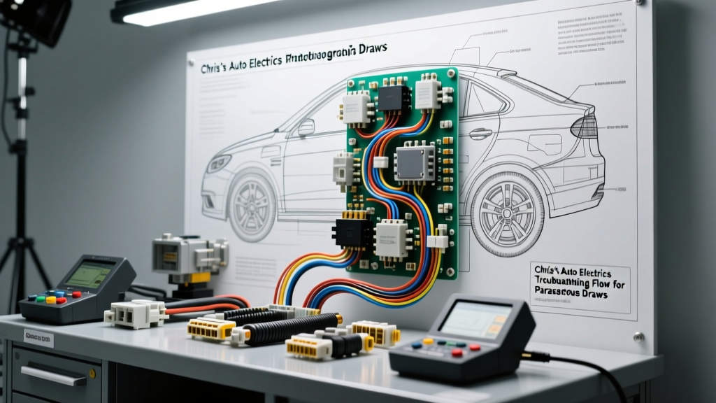
Introduction to the Chris's Auto Electrics Methodology
When diagnosing complex parasitic battery drains and intermittent charging system faults, relying on guesswork or blindly pulling fuses leads to misdiagnosis and unnecessary parts replacement. The Chris's Auto Electrics troubleshooting flow is a highly respected, systematic methodology utilized by master technicians to isolate electrical faults without disrupting module sleep states or altering circuit resistance. By prioritizing non-invasive voltage drop testing and precise digital multimeter (DMM) verification, this framework ensures accurate diagnostics on modern multiplexed vehicle architectures. This guide breaks down the exact step-by-step troubleshooting flow used to conquer the most stubborn battery drain and alternator ripple issues.
Phase 1: Preparation and Baseline Voltage Testing
Before initiating the isolation flow, you must establish a verified baseline. Modern vehicles feature dozens of control modules that can take up to 45 minutes to enter a low-power "sleep" state after the ignition is turned off and the doors are closed. Interrupting this process by opening a door or disconnecting the battery prematurely will invalidate your parasitic draw readings.
Step-by-Step Baseline Verification
- Surface Charge Removal: Turn on the high-beam headlights for 60 seconds with the engine off to remove the surface charge from the battery plates.
- Resting Voltage Check: Connect your DMM to the battery posts (not the clamps). A fully charged flooded lead-acid battery should read 12.60V to 12.66V at 70°F (21°C). An AGM battery should read slightly higher, around 12.73V to 12.80V.
- Conductance Testing: Use a dedicated carbon pile or digital conductance tester to verify the battery's Cold Cranking Amps (CCA) meet the OEM specification. A battery with a failed internal cell will mimic a parasitic draw by self-discharging rapidly.
- Inductive Clamp Setup: Clamp a high-resolution DC current clamp around the negative battery cable. Ensure the clamp is zeroed and positioned away from alternating magnetic fields.
Phase 2: Non-Invasive Voltage Drop Isolation Flow
The hallmark of the Chris's Auto Electrics methodology is avoiding the "pull-and-wait" fuse test. Pulling fuses can wake up sleeping modules via the CAN bus, resetting the sleep timer and masking the offending circuit. Instead, we measure the micro-voltage drop (mV) across the top test points of each fuse while the circuit remains closed and under load.
Set your DMM to the millivolt DC (mV DC) scale. Place the red probe on one test point of the fuse and the black probe on the other. The resistance of the fuse element creates a minute voltage drop proportional to the current flowing through it. Use the reference table below to convert your mV reading to amperage.
Fuse Voltage Drop to Amperage Conversion Chart
| Fuse Type / Rating | Approx. mV Drop per 100mA | Target mV for 50mA Draw | Common Circuit Application |
|---|---|---|---|
| Mini / 10A | 1.50 mV | 0.75 mV | Interior Lighting, Radio Memory |
| Mini / 15A | 1.20 mV | 0.60 mV | ECM Keep-Alive, OBD2 DLC Power |
| ATO / 20A | 0.80 mV | 0.40 mV | Power Windows, Seat Modules |
| ATO / 30A | 0.55 mV | 0.27 mV | HVAC Blower, ABS Module Standby |
| Maxi / 40A | 0.40 mV | 0.20 mV | Starter Relay Feed, Main IGN |
Note: If your total measured parasitic draw exceeds 50mA (0.050A) after all modules have entered sleep mode, locate the fuse exhibiting the highest proportional mV drop. This isolates the faulty circuit without waking the network.
Phase 3: Alternator Ripple and Rectifier Bridge Verification
A hidden cause of battery depletion and electrical noise is a failed diode within the alternator's rectifier bridge. A single shorted or open diode will allow AC voltage to leak into the vehicle's DC electrical system, causing severe interference and draining the battery via the stator windings when the engine is off.
Testing the Alternator B+ and Sense Circuits
Before testing ripple, verify the physical integrity of the alternator connections. The main B+ output terminal typically utilizes a 6 AWG or 8 AWG red wire secured with an M8 nut. This nut must be torqued to 15 Nm (11 lb-ft) to prevent micro-arcing and voltage drop under high-load conditions (e.g., 140A output during heavy steering and AC use).
Next, inspect the voltage regulator connector. On common Denso 4-pin alternators, the pinout is as follows:
- Pin 1 (L - Lamp/Field): 18 AWG, typically Yellow/Red. Provides the initial excitation current from the ignition switch.
- Pin 2 (IG - Ignition): 18 AWG, Black/Orange. Signals the regulator that the engine is running.
- Pin 3 (S - Sense): 14 AWG, White/Red. This is the most critical wire for charging accuracy. It routes directly to the battery positive or main fuse box to monitor actual system voltage. If this 14 AWG wire suffers corrosion or a high-resistance splice, the alternator will overcharge, boiling the battery.
- Pin 4 (P - Phase): Stator input, monitors internal alternator RPM.
AC Ripple Measurement
- Start the engine and turn on all major electrical loads (headlights, rear defroster, HVAC blower on high) to force the alternator to its maximum output.
- Switch your DMM to AC Volts (VAC).
- Place the probes directly on the alternator B+ terminal and the alternator case ground.
- Acceptable Ripple: Less than 50mV (0.050V) AC.
- Failure Threshold: Anything above 100mV AC indicates a failed rectifier diode trio or a slipping serpentine belt causing harmonic AC noise. For definitive proof, reference the waveform patterns available in the Pico Technology Automotive Waveforms Library to visually identify the missing peaks of a failed diode using an oscilloscope.
Phase 4: CAN Bus Sleep Mode and Termination Diagnostics
If the voltage drop flow in Phase 2 reveals a draw on a module-heavy circuit (like the BCM or Gateway module), but no single component is at fault, the vehicle's CAN bus network may be failing to enter sleep mode. A single corrupted message or a shorted transceiver will keep the entire network awake, resulting in a parasitic draw of 300mA to 800mA.
OBD2 DLC Network Verification
Access the Data Link Connector (DLC) under the dashboard to test the high-speed CAN network (ISO 15765-4).
- Pin 6 (CAN-High): Should read approximately 2.6V DC when active, and drop to 2.5V or 0V when asleep (depending on OEM transceiver design).
- Pin 14 (CAN-Low): Should read approximately 2.4V DC when active, and rise to 2.5V or 0V when asleep.
Termination Resistance Check
With the battery disconnected and the vehicle fully powered down, set your DMM to Ohms (Ω). Measure the resistance between DLC Pin 6 and Pin 14. The CAN bus requires a 120-ohm terminating resistor at each end of the network (usually inside the ECM and the BCM). Because these two 120-ohm resistors are wired in parallel, your DMM must read exactly 60 ohms.
If you read 120 ohms, one terminating resistor is open or a module is missing. If you read less than 60 ohms (e.g., 40 ohms), there is an aftermarket device (like a poorly wired GPS tracker or alarm system) spliced into the CAN bus, or a short between the twisted pair wires (often 18 AWG Orange/Green and Orange/Brown). For deeper network topology standards, consult the SAE International Standards documentation on vehicle network architectures.
Troubleshooting Decision Tree Summary
- Symptom: Battery dead after 48 hours. Test: Measure resting voltage. Result: 11.8V. Action: Proceed to Phase 2 mV drop testing.
- Symptom: Headlights pulse at idle. Test: Measure AC Ripple at B+. Result: 250mV AC. Action: Replace alternator rectifier bridge or complete unit.
- Symptom: Draw remains at 450mA after all fuses checked. Test: Check DLC Pins 6/14 resistance. Result: 52 Ohms. Action: Locate unauthorized aftermarket splice on CAN-H/CAN-L twisted pair.
By strictly adhering to the Chris's Auto Electrics troubleshooting flow, technicians can eliminate variables, protect sensitive OEM modules, and accurately pinpoint electrical faults using empirical data rather than assumptions. For further reading on alternator control strategies and multiplexed systems, the Bosch Mobility Solutions technical archives provide excellent OEM-level schematics and diagnostic criteria.