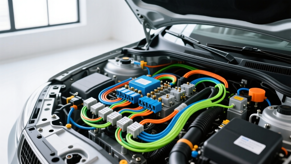
The Enrique Auto Electric Standard: Why DIY Wiring Fails
Modern automotive electrical systems are highly sensitive, multiplexed networks that demand precision, proper material selection, and strict adherence to safety protocols. When master technicians at professional facilities like Enrique Auto Electric pull back the electrical tape on a DIY wiring project, they frequently uncover undersized cables, improper grounds, and bypassed safety circuits. These mistakes do not just cause annoying parasitic draws or dim headlights; they are the leading cause of vehicle electrical fires and catastrophic ECU (Engine Control Unit) failures.
Whether you are installing an electric AC compressor, upgrading an alternator for a high-output audio system, or repairing a frayed starter circuit, understanding the common pitfalls is critical. This guide outlines the most severe wiring mistakes and the non-negotiable safety warnings that define the Enrique Auto Electric standard of excellence.
Mistake #1: Ignoring Voltage Drop in High-Amperage Circuits
One of the most frequent errors seen in aftermarket installations is selecting wire gauges based solely on the amperage rating, while completely ignoring the length of the wire run. According to the SAE J1128 Standard for low-tension primary cables, wire resistance increases with length, leading to voltage drop and excessive heat generation.
For example, upgrading to a 200-amp alternator to support auxiliary lighting or a winch requires more than just a standard 8 AWG battery cable. If the run from the alternator B+ terminal to the positive battery post exceeds 6 feet, an 8 AWG wire will experience a severe voltage drop, causing the alternator to overwork, overheat, and eventually fail internally.
Alternator B+ Cable Sizing Chart
| Alternator Output (Amps) | Wire Run Length (Feet) | Minimum Recommended AWG | Common Failure Mode if Undersized |
|---|---|---|---|
| 80A - 110A | 0 - 4 ft | 8 AWG | Chronic undercharging at idle |
| 110A - 140A | 4 - 7 ft | 4 AWG | Melted alternator B+ post boot |
| 140A - 180A | 7 - 10 ft | 2 AWG | Voltage regulator thermal shutdown |
| 180A - 250A+ | 10+ ft | 1/0 AWG (0 AWG) | Wire insulation fire / Alternator diode bridge failure |
Note: Always measure the exact physical routing path of the wire, not just the straight-line distance. High-strand count, oxygen-free copper (OFC) wire is mandatory for high-amperage automotive applications.
Mistake #2: The "Anywhere Ground" Fallacy
A poor ground is the root cause of 80% of all mysterious automotive electrical gremlins, including flickering dash lights, erratic fuel pump behavior, and CAN-bus communication errors. Many DIYers assume that any bolt securing a metal bracket to the chassis is a viable ground point. This is fundamentally incorrect.
Modern vehicle chassis are coated in an E-coat (electro-deposition anti-corrosion paint) that acts as a powerful electrical insulator. Grounding a high-draw component like a starter solenoid or an electric radiator fan to a painted surface creates a high-resistance connection. When current attempts to flow through this resistance, it generates intense heat, melting the connector and potentially igniting nearby plastics.
Proper Grounding Protocol
- Surface Preparation: Use a wire wheel or sandpaper to remove all paint, rust, and E-coat down to bare, shiny metal.
- Hardware Selection: Use a serrated flange ring terminal or place a star washer between the ring terminal and the chassis. The serrations must bite directly into the bare metal.
- Torque Specifications: An M8 ground stud should be torqued to 15-20 Nm; an M10 stud requires 25-35 Nm. Overtightening can snap the stud, while undertightening allows vibration to loosen the connection.
- Corrosion Protection: Apply a layer of dielectric grease over the completed connection to seal out moisture. Never apply it under the terminal, as it will impede current flow.
Mistake #3: Miswiring ISO Relays and Bypassing Fuses
When adding accessories like off-road light bars or electric fuel pumps, relying on a simple dashboard toggle switch to carry the full load is a recipe for a melted dashboard harness. Relays are mandatory, yet the standard ISO 7588 5-pin Bosch-style relay is frequently miswired. As detailed in the Auto Shop 101 Relay Guide, understanding the pinout is critical for safe operation.
Standard ISO 5-Pin Relay Pinout & Wire Colors
- Pin 30 (Common / B+ Input): Connects directly to the battery positive via an appropriately sized inline fuse. Wire Color: Heavy Red (e.g., 10 AWG).
- Pin 87 (Normally Open / Load Output): Sends power to the accessory when the relay is energized. Wire Color: Color-coded to the specific accessory circuit.
- Pin 85 (Coil Ground): Connects to a clean chassis ground. Wire Color: Black (18 AWG).
- Pin 86 (Coil 12V Trigger): Connects to the low-amperage dashboard switch or ECU trigger signal. Wire Color: Switched Ignition color (e.g., Pink/White).
- Pin 87a (Normally Closed): Unused in most standard accessory circuits; leave capped to prevent short circuits.
The Fatal Mistake: Bypassing the inline fuse on Pin 30. If the wire from the battery to Pin 30 chafes against the exhaust manifold or a sharp firewall edge, a direct dead-short to ground will occur. Without a fuse, the wire will glow red hot and ignite the vehicle within seconds.
Mistake #4: Soldering Under-Hood Connections
While soldering is excellent for stationary electronics, it is highly discouraged for under-hood automotive wiring. Solder is rigid and lacks the tensile flexibility of copper strands. The extreme vibration of an internal combustion engine, combined with severe thermal cycling (-20°F to 220°F+), causes soldered joints to suffer from metal fatigue and micro-fractures.
Furthermore, solder exhibits capillary action. If applied to a crimped terminal, the solder wicks up into the wire insulation, creating a stiff, brittle section of wire right at the exit point of the connector. This is the exact point where vibration stress is highest, leading to a guaranteed wire break. The industry standard is to use high-quality, open-barrel or closed-barrel crimpers, followed by sealing the connection with adhesive-lined (dual-wall) heat shrink tubing.
Critical Safety Warnings Before Touching a Wire
Beyond poor workmanship, failing to respect the safety systems integrated into modern vehicles can result in severe personal injury or thousands of dollars in module damage. Adhering to the Enrique Auto Electric safety checklist requires strict observance of the following warnings:
1. SRS (Airbag) System Protocols
Any wire wrapped in a yellow loom or featuring yellow connectors is part of the Supplemental Restraint System (SRS). These circuits use a low-current, high-sensitivity squib to deploy airbags. A standard digital multimeter (DMM) outputs enough voltage during a continuity test to accidentally deploy an airbag or seatbelt pretensioner. Never probe an SRS circuit with a standard DMM. Furthermore, after disconnecting the negative battery terminal, you must wait a minimum of 15 minutes for the SRS backup capacitor to discharge before working near steering columns or dash panels, as mandated by NHTSA Airbag Safety Protocols.
2. Alternator Exciter Wire Sensitivity
When replacing alternators on vehicles like the GM CS130 or Ford 3G systems, the small gauge exciter wires (often the 'L' or 'I' terminals) are directly tied to the ECU or Body Control Module (BCM). Accidentally grounding the 'L' terminal wire while the ignition is on can instantly fry the driver inside the alternator voltage regulator or send a voltage spike back into the BCM. Always use insulated tools and disconnect the negative battery cable before removing alternator B+ nuts.
3. High-Voltage EV and Hybrid Systems
If you are transitioning from traditional 12V systems to hybrid or electric vehicles, recognize that orange cabling indicates high-voltage DC systems ranging from 200V to over 800V. These systems require specialized insulated tools (rated for 1000V), high-voltage lineman gloves, and the physical removal of the manual service disconnect (MSD) plug before any 12V auxiliary work is performed near the inverter or traction battery.
Conclusion
Automotive electrical work leaves zero margin for error. By avoiding undersized cables, ensuring bare-metal grounding, properly wiring ISO relays, and respecting SRS and high-voltage safety boundaries, you protect both yourself and the vehicle. The principles championed by professionals at Enrique Auto Electric are not just suggestions; they are the fundamental laws of automotive physics and safety. Invest in proper crimping tools, adhere to AWG length charts, and never bypass a fuse.